TEST 4: Testing The Power (12 Volts) Circuit

The ignition coil pack needs 10 to 12 Volts to function and its the red with light green stripe (RED/LT GRN) that delivers them.
We'll do a simple multimeter voltage test to see if the RED/LT GRN wire is delivering them when the key on engine off (KOEO).
NOTE: Be careful when probing the front of the terminal with your multimeter test leads, or you could damage it (and then you'll need to replace the entire connector).
Let's get going:
- 1
Disconnect the ignition coil from its connector.
- 2
Put the multimeter in Volts DC mode.
- 3
Connect the black multimeter test lead to the battery negative (-) terminal.
- 4
Gently probe the front of the female terminal that connects to the RED/LT GRN wire with the red multimeter test lead (using an appropriate tool).
- 5
Have your helper turn the key to the ON position (no need to crank the engine).
- 6
You should see 10-12 Volts on your multimeter.
Let's find out what your test result means:
CASE 1: The multimeter registered 10 to 12 Volts DC. This is the correct test result.
Since you've reached this test section because none of the spark plug wires sparked, the next step is to check that the PCM is providing an activation signal to each of the 3 individual coils that make up the ignition coil pack. Go to: TEST 8: Checking The IC Activation Signals.
CASE 2: The multimeter DID NOT register 10 to 12 Volts DC. Re-check all of your connections and retest.
If still no voltage is present, this result exonerates the coil pack. Repairing the cause of this missing voltage will solve the 'no-spark no-start' condition of your Ford E150 or E250.
TEST 5: Activation Signal For Cylinders 1 And 5

Checking the activation signal for the ignition coil (IC) that fires spark to cylinders 1 and 5, can be done easily with a 12 Volt automotive test light (non-powered test light).
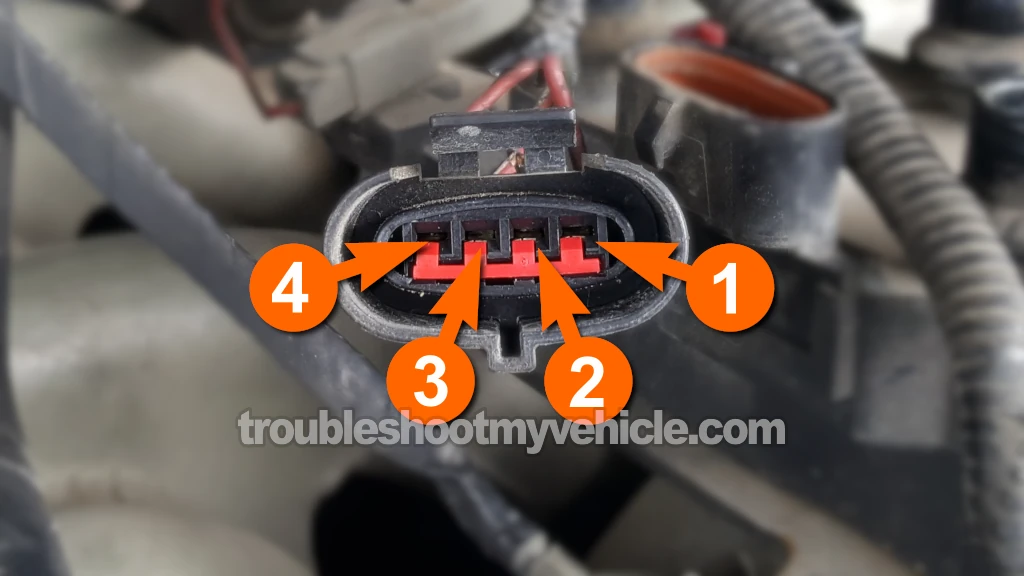
The dark blue with light green stripe wire (DK BLU/LT GRN) of the ignition coil's 4-wire connector delivers the activation signal for cylinder 1 and 5 ignition coil.
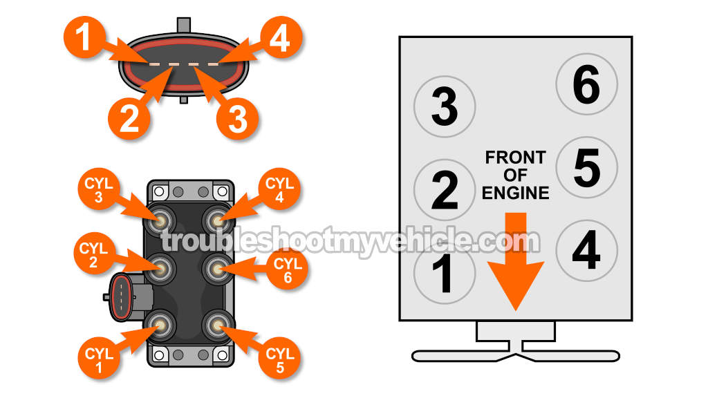
The DK BLU/LT GRN wire connects to the terminal labeled with the number 2 in the photo above
IMPORTANT: Be careful not to damage the female terminal or the connector with your 12V test light's probing tip. If the terminal or the connector get damaged, you'll need to replace the connector.
CAUTION: This test has to be performed with the engine cranking. Be careful and take all necessary safety precautions.
Alright, let's start:
- 1
Disconnect the ignition coil from its 4-wire electrical connector.
- 2
Connect the 12V test light's alligator clip to the battery positive (+) post.
- 3
With the test light's probing tip, gently probe terminal number 2.
Terminal number 2 should connect to the DK BLU/LT GRN wire. - 4
Have your helper crank the engine.
- 5
The 12V test light should flash ON and OFF the whole time the engine is cranking.
Let's find out what your test result means:
CASE 1: The 12V test light flashed ON and OFF the whole time the engine was cranking. With this test result you can conclude that the PCM is providing the cylinder 1/5 activation signal and the circuit is OK.
You can conclude that the ignition coil pack is bad if you have:
- Confirmed that the spark plug wires for cylinders 1 and 5 are not sparking (TEST 1).
- Confirmed that the ignition coil towers for cylinders 1 and 5 are not sparking (TEST 3).
- Confirmed that the ignition coil pack is receiving the cylinder 1/5 activation signal from the fuel injection computer (this test section).
CASE 2: The 12V test light DID NOT flash ON and OFF the whole time the engine was cranking. This test result usually means that there's either an open-circuit in the circuit between the connector and the PCM or the PCM is fried (altho' very rare).
With this result you have eliminated the coil pack itself as the source of the misfire condition or no-spark condition. Your next step is to resolve the issue causing this missing IC activation signal.
