
Testing the ignition control module (ICM) on the 1994-2005 3.1L V6 Buick Century is really a very simple process! The best part of all, is that you don't need any expensive or exotic diagnostic tools to get it done.
In this tutorial, I'm gonna help you diagnose an engine no-start condition caused by a complete loss of spark on your 1994-2005 3.1L V6 Buick Century.
The tests in this tutorial will help you verify whether the ignition control module (ICM) is receiving everything it needs to operate correctly or if the real troublemaker is the 7X crankshaft position (CKP) sensor.
Contents of this tutorial:
- Basic Operating Theory Of The Ignition Control Module.
- Circuit Descriptions Of The Ignition Control Module.
- Before You Begin Testing The Ignition Control Module.
- TEST 1: Making Sure The ICM Is Getting Power.
- TEST 2: Making Sure The ICM Is Getting Ground.
- TEST 3: Making Sure The ICM Is Getting The 7X CKP Sensor Signal.
- TEST 4: CKP Sensor Resistance Test.
- Where To Buy The Ignition Module Or CKP Sensor And Save.
- More 3.1L V6 Buick Century Diagnostic Tutorials.
ES  You can find this tutorial in Spanish here: Cómo Probar El Módulo De Encendido (1994-2005 3.1L V6 Buick Century) (at: autotecnico-online.com).
APPLIES TO: This tutorial applies to the following vehicles:
- 3.1L V6 Buick Century: 1994, 1995, 1996, 1997, 1998, 1999, 2000, 2001, 2002, 2003, 2004, 2005.
IGNITION CONTROL MODULE (ICM) WIRING DIAGRAM:
- ICM And 3X CKP Sensor Circuit Wiring Diagram (1994-1995 3.1L V6 Buick Century).
- ICM And 7X CKP Sensor Circuit Wiring Diagram (1996 3.1L V6 Buick Century).
- ICM And 7X CKP Sensor Circuit Wiring Diagram (1997 3.1L V6 Buick Century).
- ICM And 7X CKP Sensor Circuit Wiring Diagram (1998-2005 3.1L V6 Buick Century).
OTHER IGNITION SYSTEM DIAGNOSTIC TESTS:
- How To Test The Ignition Coil Packs (1994-2005 3.1L V6 Buick Century).
- How To Test The 7X Crankshaft Position Sensor (1994-2005 3.1L V6 Buick Century).
- How To Test The 24X Crankshaft Position Sensor (1994-2005 3.1L V6 Buick Century).
Basic Operating Theory Of The Ignition Control Module
The ignition control module (ICM) is responsible for firing the three ignition coils that sit on top of it. It does this by supplying each ignition coil with battery voltage and a Switching signal (activation signal), which causes the coil to produce spark.
If you're wondering what a Switching signal is, it's simply the ignition control module rapidly turning the ignition coil's Ground circuit ON and OFF. Every time the Ground circuit is switched, the ignition coil produces a high-voltage spark.
For the ignition control module to generate this Switching signal, it needs three things:
- Battery power (12 Volts).
- A good Ground.
- A 7X crankshaft position (CKP) sensor signal.
Here's what happens when you crank the engine:
- The ignition control module receives battery power and Ground.
- As the engine begins to crank, the 7X crankshaft position (CKP) sensor generates its crankshaft position signal.
- The ignition control module uses the CKP sensor signal to begin generating Switching signals for the three ignition coils, causing them to produce spark in the correct firing order.
- While the engine is cranking and below approximately 400 RPM, the ignition control module controls ignition timing by itself.
- Once engine speed exceeds about 400 RPM, the PCM takes over ignition timing while the ignition control module continues switching the ignition coils ON and OFF.
As you'll see in this tutorial, if the ignition control module loses battery power, Ground, or the CKP sensor signal, it won't generate the Switching signals needed to fire the ignition coils.
ENGINE NO-START DIAGNOSTICS: Troubleshooting an engine cranks but does not start? This tutorial walks you through a proven step-by-step diagnostic process to help you pinpoint the exact cause:
CYLINDER MISFIRE DIAGNOSTICS: Got a cylinder misfire? This step-by-step guide will help you track down the cause:
Circuit Descriptions Of The Ignition Control Module
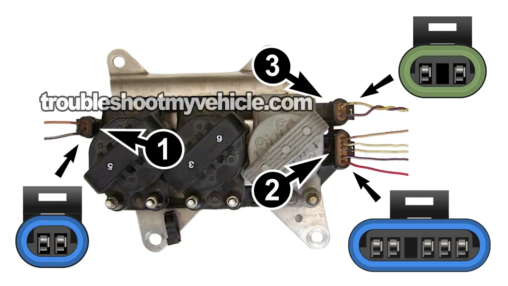
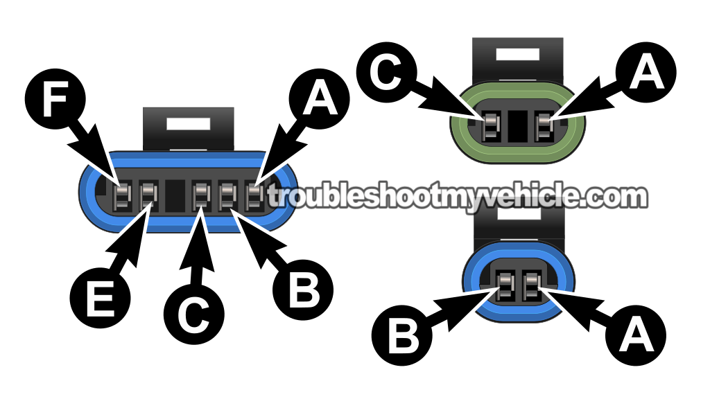
Before we begin testing the ignition control module, let's take a quick look at the circuits we'll be working with.
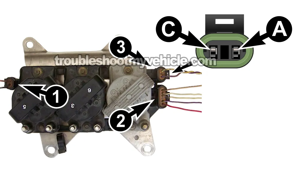
In the photo above, I've labeled the ignition control module's three electrical connectors with the numbers 1, 2, and 3. Although the module has three connectors, the tests in this tutorial only require the circuits found in Connectors 1 and 2. I've included the circuit descriptions for Connector 3 for reference.
The wire colors remained essentially the same throughout the 1994-2005 model years. Even so, if the wire colors on your vehicle don't seem to match the descriptions below, I recommend comparing them to the appropriate wiring diagram for your specific model year (I've included links to the wiring diagrams below).
IMPORTANT: If your Buick Century isn't equipped with a tachometer, Connector 3 won't contain all of the wires shown below. This is normal. The missing wire is the tachometer signal circuit.
Each terminal in the ignition control module connectors is identified by a letter molded into the connector housing. I'll use those same terminal letters in the circuit descriptions below.
Connector 1
- A —Pink (PNK) wire. Battery power (12 Volts with the ignition key ON).
- B —Black (BLK) or black with white stripe (BLK/WHT) wire. Chassis Ground.
Connector 2
- A —Tan with black stripe (TAN/BLK) wire. 5-Volt reference from the PCM (above 400 RPM).
- B —White (WHT) wire. PCM ignition timing control signal (above 400 RPM).
- C —White (WHT) wire. Tachometer signal (if equipped).
- D —Empty. No circuit.
- E —Purple with white stripe (PPL/WHT) wire. Fuel control circuit.
- F —Red with black stripe (RED/BLK) wire. PCM Ground.
Connector 3
- A —Yellow (YEL) wire. 7X CKP sensor signal.
- B —Empty. No circuit.
- C —Purple (PPL) wire. 7X CKP sensor signal.
As you'll see in the following tests, you won't need to check every circuit listed above. We'll only test the ones needed to determine whether the ignition control module is good or bad.
Before You Begin Testing The Ignition Control Module
This tutorial focuses on diagnosing an engine no-start condition caused by a complete loss of spark at all six spark plug wires.
Before we begin, it's important to understand that the ignition control module (ICM) usually fails in one of two ways:
- Engine misfire: The ICM stops activating one of the three ignition coil packs, causing only two cylinders to lose spark.
- Engine no-start: The ICM stops activating all three ignition coil packs, causing all six cylinders to lose spark.
In this tutorial, we're diagnosing the second condition: an engine no-start caused by a complete loss of spark.
Before testing the ignition control module, you first need to determine which ignition coils are producing spark and which ones aren't. If you haven't already checked for spark at all six spark plug wires, I recommend doing that first.
The easiest way to do this is by following my ignition coil pack testing tutorial:
Once you've completed those tests, you'll usually find yourself in one of these two situations:
- One ignition coil isn't producing spark: This usually indicates a problem with that ignition coil or the ignition control module circuit that controls it.
- None of the three ignition coils are producing spark: This can be caused by a failed ignition control module or by the ignition control module not receiving the 7X crankshaft position (CKP) sensor signal it needs to fire the ignition coils.
In this tutorial, we'll verify that the ignition control module has everything it needs to operate correctly. Specifically, we'll check:
- Battery power (12 Volts).
- A good Ground.
- The 7X crankshaft position (CKP) sensor signal.
Once you've completed these tests, you'll know whether the ignition control module has failed or whether the real problem is the missing 7X CKP sensor signal.
IMPORTANT: All of the tests in this tutorial are performed with the ignition control module installed on the engine. Some of the photos show the ignition control module removed from the vehicle to make it easier to identify the terminals being tested. Do not remove the ignition control module unless the test instructions specifically tell you to do so.
TEST 1: Making Sure The ICM Is Getting Power
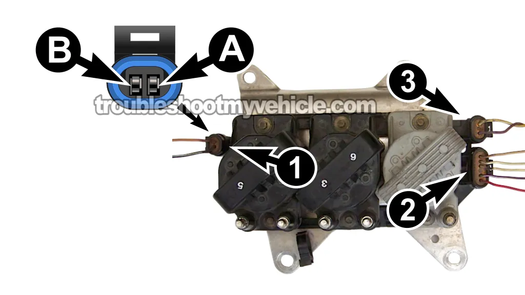
The first thing we're going to verify is that the ignition control module is receiving battery power.
You can perform this test with a multimeter or even a test light (I prefer using a multimeter).
IMPORTANT: All of the tests in this tutorial are performed with the ignition control module installed on the engine. The photos show the module removed from the vehicle only to make it easier to identify the terminals and circuits. Do not remove the ignition control module to perform this test.
Let's get started:
- 1
Set your multimeter to Volts DC.
- 2
Disconnect Connector 1 from the ignition control module.
- 3
Connect the black multimeter lead to the battery negative (-) terminal.
- 4
Gently probe the female terminal that connects to the PNK wire of the connector with the red multimeter lead.
This wire connects to terminal A of Connector 1 (see the photo above). - 5
Turn the ignition key to the ON position. Do not crank the engine.
- 6
Your multimeter should measure 10 to 12 Volts.
Here's what your test results mean:
CASE 1: Your multimeter measured 10 to 12 Volts. This is the expected result and confirms that the ignition control module is receiving battery power.
Your next step is to verify that the ignition control module has a good Ground. Go to: TEST 2: Making Sure The ICM Is Getting Ground.
CASE 2: Your multimeter did not measure 10 to 12 Volts. This tells you the ignition control module isn't receiving battery power.
Without battery power, the ignition control module cannot operate and the engine won't produce spark.
In most cases, the cause is an open fuse or an open in the power supply circuit. Repair the problem, restore battery power to the ignition control module, and retest the system.
TEST 2: Making Sure The ICM Is Getting Ground
Now that you've verified the ignition control module is receiving battery power, the next step is to make sure it has a good Ground.
The Ground is delivered to the ignition control module by the black (BLK) wire of Connector 1 (see the photo above).
Since this is a chassis Ground, it should be present at all times, regardless of whether the ignition key is ON or OFF.
Let's begin:
- 1
Set your multimeter to Volts DC.
- 2
Disconnect Connector 1 from the ignition control module.
- 3
Connect the red multimeter lead to the battery positive (+) terminal.
- 4
Probe the BLK wire with the black multimeter lead.
This wire connects to terminal B of Connector 1 (see the photo above). - 5
Your multimeter should measure 10 to 12 Volts.
Here's what your test results mean:
CASE 1: Your multimeter measured 10 to 12 Volts. This is the expected result and confirms that the ignition control module has a good Ground.
Your next step is to verify that the ignition control module is receiving the 7X crankshaft position (CKP) sensor signal. Go to: TEST 3: Making Sure The ICM Is Getting The 7X CKP Sensor Signal.
CASE 2: Your multimeter did not measure 10 to 12 Volts. This tells you the ignition control module isn't receiving Ground.
Without a good Ground, the ignition control module cannot operate or fire the ignition coils. Since you've already verified that the module is receiving battery power, you can rule out the ignition control module itself as the cause of the no-start condition.
In most cases, the problem is an open Ground circuit or a poor Ground connection. Repair the Ground circuit, then repeat the ignition system tests.
TEST 3: Making Sure The ICM Is Getting The 7X CKP Sensor Signal
By this point, you've already verified that the ignition control module is receiving battery power and has a good Ground. The last thing it needs to operate is the 7X crankshaft position (CKP) sensor signal.
If this signal is missing, the ignition control module won't activate any of the ignition coils, even though it has power and Ground.
In this test, you'll use a multimeter set to AC Volts to verify that the 7X CKP sensor is generating its signal while the engine is cranking.
IMPORTANT: Make sure the battery is fully charged before performing this test. A weak battery can affect the AC voltage produced by the CKP sensor.
You'll be measuring the AC voltage across the yellow (terminal A) and purple (terminal C) wires of Connector 3 (see the photo above).
CAUTION: Since this test is performed while the engine is cranking, keep your hands, tools, and clothing away from any moving engine components.
NOTE: You can find a more detailed explanation of how to test the 7X CKP sensor in this tutorial: How To Test The 7X Crankshaft Position Sensor (1994-2005 3.1L V6 Buick Century).
Let's get started:
- 1
Set your multimeter to AC Volts.
- 2
Disconnect Connector 3 from the ignition control module.
- 3
Connect the red multimeter lead to the YEL wire (terminal A).
- 4
Connect the black multimeter lead to the PPL wire (terminal C).
- 5
Have your helper crank the engine while you observe the multimeter.
- 6
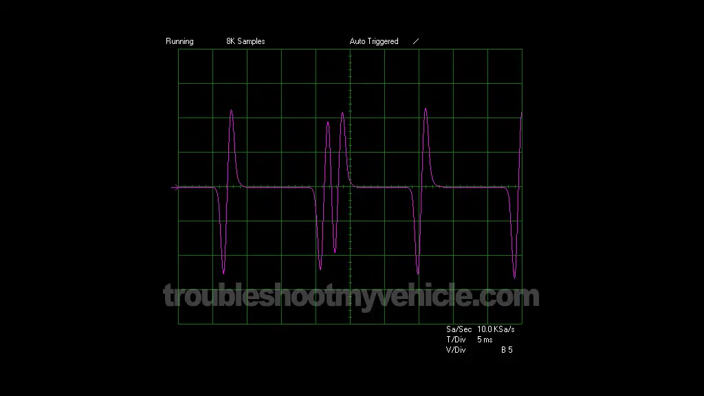
The multimeter should display a continuously changing AC voltage of approximately 0.3 to 1.0 Volts AC.
The exact voltage depends on engine temperature, battery condition, and cranking speed.
If you're using an oscilloscope instead of a multimeter, the waveform should resemble the one shown in image 2 of 2 in the image viewer above.
Here's what your test results mean:
CASE 1: Your multimeter measured an AC voltage. This confirms that the 7X CKP sensor is producing its signal.
Since you've already verified that the ignition control module has battery power and Ground, this result points to the ignition control module as the most likely cause of the no-spark condition.
Before replacing it, however, perform one final test by checking the resistance of the 7X CKP sensor. Go to: TEST 4: CKP Sensor Resistance Test.
CASE 2: Your multimeter did not measure an AC voltage. First, verify your multimeter connections and repeat the test.
If the AC voltage is still missing, don't replace the 7X CKP sensor just yet. One of the most common causes of this condition is damaged CKP sensor wiring.
The 7X CKP sensor connects to the ignition control module through two twisted wires that run beneath the rear exhaust manifold. Over time, the retaining clips can break, allowing the harness to contact the hot exhaust manifold or rub against the engine block. This can damage the insulation and short one or both wires to Ground, preventing the CKP signal from reaching the ignition control module.
Inspect the wiring carefully before replacing the sensor. If the wiring is damaged, you can repair it or replace the harness instead of replacing the CKP sensor unnecessarily.
TEST 4: CKP Sensor Resistance Test
In TEST 3, you verified that the 7X crankshaft position (CKP) sensor is producing an AC voltage signal while the engine is cranking. In most cases, that's enough to rule out the CKP sensor and point to a faulty ignition control module.
Over the years, however, a few readers have reported cases where the CKP sensor produced an AC voltage signal but was still defective. For that reason, I recommend one final test before replacing the ignition control module.
Since the 7X CKP sensor is mounted in a difficult-to-reach location on the engine block, you'll measure its resistance from Connector 3 of the ignition control module instead of disconnecting the sensor itself.
Let's get started:
- 1
Set your multimeter to Ohms (Ω).
- 2
Disconnect Connector 3 from the ignition control module.
- 3
Connect the red multimeter lead to the YEL wire (terminal A).
- 4
Connect the black multimeter lead to the PPL wire (terminal C).
- 5
The resistance should measure between 500 and 900 Ohms.
Here's what your test results mean:
CASE 1: The resistance measured between 500 and 900 Ohms. This is the expected result and confirms that the 7X CKP sensor is within specification.
If you've also confirmed the following:
- All six spark plug wires did not produce spark.
- The ignition control module is receiving battery power (TEST 1).
- The ignition control module has a good Ground (TEST 2).
- The 7X CKP sensor is producing an AC voltage signal (TEST 3).
- The 7X CKP sensor resistance is within specification (this test).
...then you can confidently conclude that the ignition control module is defective and needs to be replaced.
CASE 2: The resistance was outside the specified range. Verify your multimeter connections and repeat the test.
If the resistance is still outside the 500 to 900-Ohm specification, you can conclude that the 7X CKP sensor is defective and needs to be replaced.
Where To Buy The Ignition Module Or CKP Sensor And Save
The following links will help you comparison shop for the Delphi and Standard ignition control module and crankshaft position sensor:


Disclosure: As an Amazon Associate, I earn from qualifying purchases. If my tutorials help you, using these links is an easy way to support the site at no extra cost to you. Thank you!
Not sure if the above ignition module and/or CKP sensor fit your particular GM vehicle? Don't worry, once you get to the site they'll make sure it fits. If it doesn't, they find you the right part.
More 3.1L V6 Buick Century Diagnostic Tutorials
If this tutorial was helpful, there's plenty more, and you can find them in the following index:
Here's a sample of the tutorials you'll find in the index:
- How To Test The Fuel Pump (1994-2005 3.1L V6 Buick Century).
- How To Test The TPS With A Multimeter (1997-2005 3.1L V6 Buick Century).
- Common Causes Of Spark Plug Failure (1994-2005 3.1L V6 Buick Century).
- How To Test Engine Compression (1994-2005 3.1L V6 Buick Century).

If this info saved the day, buy me a beer!
