In this tutorial, I'll show you how to diagnose OBD-I Code 22: ECT Sensor Voltage Too Low or Too High —the same way a professional automotive technician would.
This is a comprehensive, step-by-step guide that walks you through every test needed to pinpoint the problem accurately.
You won't need any expensive tools —just a digital multimeter and a little patience. I've designed every test (in this guide) to be simple, reliable, and 100% doable for the home mechanic/DIYer.
Contents of this tutorial:
- Symptoms Of A Bad ECT Sensor.
- Where To Buy The ECT Sensor And Connector.
- Should You Just Replace The ECT Sensor Without Testing It?
- TEST 1: Check For 5 Volt Reference At The ECT Sensor Connector.
- TEST 2: Check The Resistance Of The ECT Sensor.
- TEST 3: Isolate Whether The 5 Volt Reference Or The Sensor Ground Is Missing.
- TEST 4: Check ECT Sensor Resistance From The PCM Connector (Wiggle Test).
- TEST 5: Check Continuity From ECT Connector To PCM (5 Volt and Ground Wires).
- TEST 6: Checking For Shorts Between ECT Wires Or To Ground.
- What If The PCM Itself Is Bad?
- Watch Out For Shared Sensor Ground Circuits.
- More 5.2L, 5.9L V8 Dodge Ram Pickup Tutorials.
APPLIES TO: This tutorial applies to the following vehicles:
1992-1993:
- Dodge Ram 150 Pickup 5.2L V8: 1992, 1993.
- Dodge Ram 250 Pickup 5.2L V8: 1992, 1993.
- Dodge Ram 150 Pickup 5.9L V8: 1993.
- Dodge Ram 250 Pickup 5.9L V8: 1993.
- Dodge Ram 350 Pickup 5.9L V8: 1993.
1994-1995:
- Dodge Ram 1500 Pickup 5.2L V8: 1994, 1995.
- Dodge Ram 2500 Pickup 5.2L V8: 1994, 1995.
- Dodge Ram 1500 Pickup 5.9L V8: 1994, 1995.
- Dodge Ram 2500 Pickup 5.9L V8: 1994, 1995.
- Dodge Ram 3500 Pickup 5.9L V8: 1994, 1995.
1996-2003 ECT SENSOR TESTS:
Symptoms Of A Bad ECT Sensor
The engine coolant temperature (ECT) sensor plays a key role in how the PCM adjusts fuel delivery, ignition timing, idle speed, and even how it controls emissions.
When this sensor fails —or when its wiring develops a problem— the PCM no longer receives accurate temperature data, which can throw off its entire engine management strategy. You might notice one or more of the following symptoms:
- Hard starts: A faulty ECT sensor can trick the PCM into thinking the engine is warmer or colder than it actually is, leading to incorrect fuel delivery during startup.
- Poor fuel economy: If the sensor reports the engine as colder than it really is, the PCM may enrich the fuel mixture unnecessarily —just like it would during a cold start— causing excessive fuel consumption.
- High idle: A bad ECT sensor may cause the PCM to keep the idle speed elevated, especially if it falsely detects a cold engine that "needs warming up".
- Check engine light with a DTC 22: The PCM will set Code 22: ECT Sensor Voltage Low or High if it detects a problem with the ECT sensor signal.
- Engine no-start: In some cases, especially when combined with other issues, a failed ECT sensor can prevent the engine from starting at all —by flooding it with fuel or delivering too little for ignition.
Where To Buy The ECT Sensor And Connector
Disclosure: As an Amazon Associate, I earn from qualifying purchases. If my tutorials help you, using these links is an easy way to support the site at no extra cost to you. Thank you!
Should You Just Replace The ECT Sensor Without Testing It?
The engine coolant temperature (ECT) sensor on these engines is located in a tight spot —tucked between the alternator and the intake manifold plenum.
Because of that, it's not easily accessible. In most cases, you'll need to either unbolt the AC compressor (and move it aside) or remove the sensor itself just to get a multimeter probe on it.
That's why a lot of folks (including auto repair shops) skip the testing and just replace the sensor outright. And honestly, I get it —the part isn't very expensive, and replacing it can be the quickest solution.
If you do opt to replace it from the get-go, don't forget to inspect the condition of the ECT sensor connector. A damaged connector or corroded pins can mimic a bad sensor and cause the exact same symptoms.
- If you've already have the ECT sensor removed, you can check it! See: TEST 2: Check The Resistance Of The ECT Sensor.
Now, if you've already replaced the ECT sensor and the same code or issue keeps coming back, the problem runs deeper.
In this tutorial, I'm going to show you how to test and diagnose the ECT circuit properly —just like a pro would— so you can get to the root of the problem and fix it for good.
TEST 1: Check For 5 Volt Reference At The ECT Sensor Connector

Before testing the sensor itself, we need to confirm that it's receiving the correct power and Ground from the PCM.
The ECT sensor is a two-wire sensor:
- One wire supplies a constant 5 Volt reference from the PCM.
- The other wire is a sensor Ground, also supplied by the PCM.
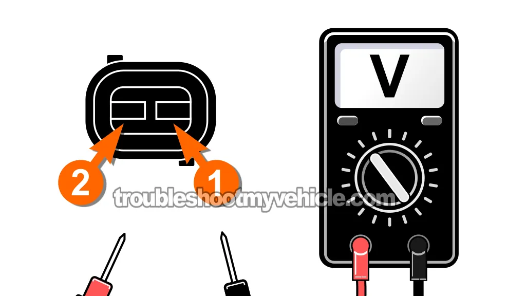
In this test, we'll unplug the ECT sensor and measure voltage across the terminals of the connector (not the sensor itself).
With the ignition key in the ON position (engine OFF), you should see a steady 5 Volts. If so, this confirms that the PCM is properly supplying both power and Ground —and that the wiring between the PCM and the ECT connector is intact.
NOTE: Don't have a multimeter or need to upgrade yours? This is the one I use and recommend: Tekpower TP8268 AC/DC Auto/Manual Range Digital Multimeter (at: amazon.com).
Here are the test steps:
- 1
Turn the ignition key to the ON position (engine OFF).
- 2
Unplug the ECT sensor.
- 3
Set your multimeter to Volts DC mode.
- 4
Probe the two female terminals of the ECT sensor connector (not the sensor).
Touch one multimeter lead to each terminal. - 5
You should see close to 5 Volts on the display.
Let's interpret your test result:
CASE 1: Your multimeter shows approximately 5 Volts. This is the correct result. The PCM is supplying the 5 Volt reference and sensor Ground correctly. Move on to: TEST 2: Check The Resistance Of The ECT Sensor.
CASE 2: Your multimeter shows 0 Volts. This indicates a wiring issue. Either the 5 Volt reference is missing, or the sensor Ground is open or damaged.
The next step is to isolate the issue further to see if it's the 5 Volts or Ground that's missing. Go to: TEST 3: Isolate Whether The 5 Volt Reference Or The Sensor Ground Is Missing.
CASE 3: You see battery voltage (12 Volts or more). This is a serious fault. It means the 5 Volt reference wire is shorted to a 12V circuit somewhere, which could potentially damage the PCM.
Your next step is to find the cause of the issue and repair it. See this article for further info (of the repair side):
TEST 2: Check The Resistance Of The ECT Sensor
Now that we've confirmed the ECT sensor is getting proper voltage and Ground from the PCM (in TEST 1), the next step is to test the sensor itself.
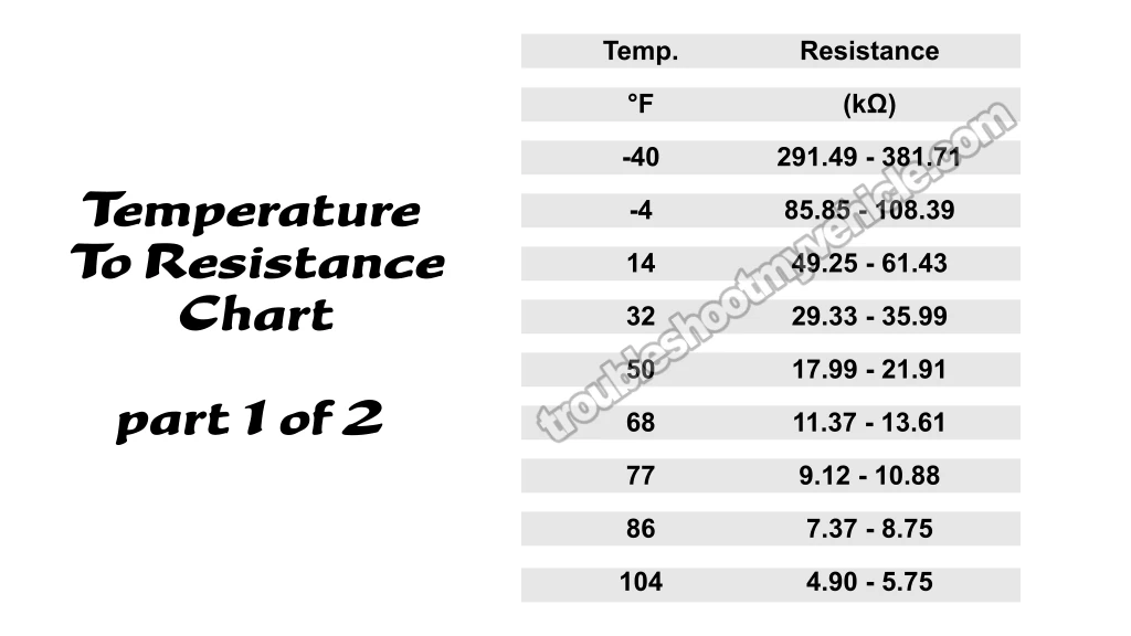
The ECT sensor is a thermistor —it changes resistance depending on temperature. When cold, resistance is high; as the engine warms up, resistance drops. In this test, we're going to check the sensor's resistance at ambient (room/outside) temperature and compare it to a temperature-to-resistance chart.
Once you have your ambient temperature, compare your sensor's resistance to the values in the ECT temperature-to-resistance chart (in the image viewer above.
The reading should be within about ±10°F of your actual ambient temp. If the resistance doesn't match up —or corresponds to a wildly different temperature— the sensor is faulty and needs to be replaced.
IMPORTANT: The engine must be cold before running this test. The temperature of the engine and sensor should match the ambient air temperature at your location. Use a weather app on your phone or a nearby wall thermometer to check your current temperature before proceeding.
NOTE: To test the ECT sensor in place, you'll need to remove the serpentine belt and unbolt the A/C compressor (4 bolts) to move it aside. You do not need to disconnect the refrigerant lines —just shift the compressor out of the way to access the sensor.
Here are the test steps:
- 1
Make sure the engine is completely cold.
By cold I mean whatever ambient temperature is around you. - 2
Disconnect the battery negative (-) terminal from the battery.
- 3
Unbolt the AC compressor and move it aside.
NOTE: DO NOT disconnect the AC compressor from its refrigerant lines. All you need to do is remove the 4 bolts that secure it to the engine and the bracket that secures it to the intake manifold. - 4
Unplug the ECT sensor.
- 5
Set your multimeter to Ohms (Ω) mode.
- 6
Measure resistance across the two terminals of the ECT sensor (not the connector, just the sensor itself).
- 7
Compare your reading to the temperature-to-resistance chart above (see the image viewer).
Your result should fall within the expected range for your current ambient temperature.
Let's interpret your test result:
CASE 1: The resistance reading matches the expected value for your ambient temperature (±10°F). This means the ECT sensor itself is functioning correctly.
Our next step is to check the ECT sensor's resistance from the FI computer's 60 pin connector. Continue to: TEST 4: Check ECT Sensor Resistance From The PCM Connector (Wiggle Test).
CASE 2: The resistance reading is significantly higher or lower than expected, and doesn't match your ambient temp. This means the ECT sensor is out of spec and reporting an incorrect engine temperature. Replace the sensor.


