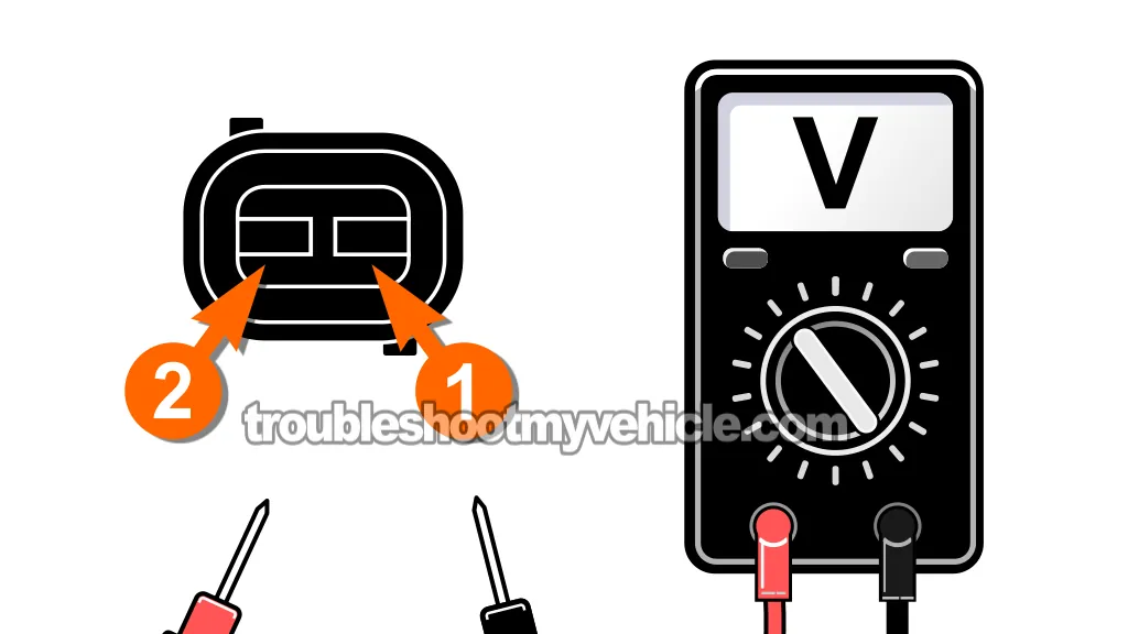
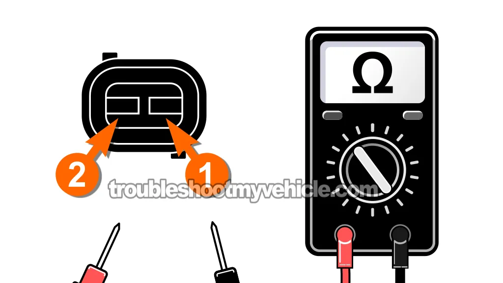
TEST 3: Isolate Whether The 5 Volt Reference Or The Sensor Ground Is Missing

If your multimeter showed 0 Volts across the ECT sensor connector terminals in TEST 1, that means something is wrong —but we don't yet know which side of the circuit is at fault.
Remember, both the 5 Volt reference and the Ground are provided by the PCM. If either one is missing, you'll see 0 Volts when testing across the two terminals.
So, in this test, we'll isolate the problem by checking each circuit individually against a known-good Ground or power source.
This will tell us whether the issue is with the 5 Volt reference wire or the sensor Ground wire —and point you toward the next step in your diagnosis.
Here are the test steps:
PART 1: 5 Volt Test
- 1
Turn the ignition key to the ON position (engine OFF).
- 2
Set your multimeter to Volts DC mode.
- 3
Probe the terminal that connects to the tan with white stripe (TAN/WHT) wire with the red multimeter test lead.
The TAN/WHT wire is the 5 Volt reference wire. - 4
Touch the other multimeter test lead to the battery negative (-) terminal.
- 5
Your multimeter should register 4.5 to 5 Volts.
PART 2: Ground Test
- 6
Probe the terminal that connects to the black with light blue stripe (BLK/LT BLU) wire with the black multimeter test lead.
The BLK/LT BLU wire is the ECT sensor Ground supply wire. - 7
Touch the other lead to the battery positive (+) terminal.
- 8
Your multimeter should read 10 to 12 Volts.
Let's interpret your test result:
CASE 1: You see 5 Volts between the 5V reference wire and a known-good Ground —but 0 Volts between the Ground wire and battery positive. This means the sensor Ground circuit is open or damaged.
The 5 Volt reference is present, but the PCM can't complete the circuit due to a missing Ground. Our next step is perform a continuity test on this circuit. Head over to: TEST 5: Check Continuity From ECT Connector To PCM (5 Volt and Ground Wires).
CASE 2: You see 10-12 Volts when testing the Ground wire to battery positive —but 0 Volts when testing the 5 Volt reference wire to Ground. This means the Ground wire is intact, but the 5 Volt reference circuit is missing.
Our next step is to check the 5V reference wire back to the PCM. Go to: TEST 5: Check Continuity From ECT Connector To PCM (5 Volt and Ground Wires).
CASE 3: You get 0 Volts on both tests. This suggests both the 5 Volt and Ground circuits are compromised.
We need to check continuity of both wires back to the PCM. Go to: TEST 5: Check Continuity From ECT Connector To PCM (5 Volt and Ground Wires).
TEST 4: Check ECT Sensor Resistance From The PCM Connector (Wiggle Test)

At this point, we've confirmed two things:
- The ECT sensor is getting the correct 5 Volt reference and Ground from the PCM (TEST 1).
- The sensor's resistance is accurate for the ambient temperature (TEST 2).
Now it's time to make sure that the resistance signal from the ECT sensor is actually making it to the PCM correctly and consistently.
This test helps us catch any intermittent issues caused by a bad ECT sensor connector or a broken wire that may not show up during a standard resistance check.
NOTE: You'll need a helper for this test. While you monitor the multimeter, your helper will gently wiggle the ECT connector and the wiring coming out of it.
IMPORTANT: In this test, you'll be probing the female terminals of the PCM's 60 pin connector. Before you begin this test, please read the important info in this article: How To Safely Probe The PCM Connector -Without Damaging It (1989-2003 5.2L, 5.9L V8 Dodge Ram Pickup).
Here are the test steps:
- 1
Make sure the engine is completely cold so the resistance reading still corresponds to ambient temperature.
- 2
Ensure the battery negative (-) terminal is still disconnected from the battery.
NOTE: This is important —never disconnect the PCM connector while the battery is still connected. Doing so can damage the PCM. - 3
Reconnect the ECT sensor to its 2-wire connector.
- 4
Disconnect the PCM 60-pin connector.
- 5
Set your multimeter to Ohms (Ω) mode.
- 6
Touch the red multimeter lead to pin 2 of the PCM 60 pin connector.
Confirm that pin 2 connects to a tan with black stripe (TAN/BLK) wire. - 6
Now, connect the black multimeter test lead to pin 4 of the PCM 60 pin connector.
Confirm that pin 4 connects to a black with light blue stripe (BLK/LT BLU) wire. - 7
Have your helper gently wiggle the ECT sensor connector and the wiring coming out of it, including the section where the wires disappear into the engine harness.
- 8
Watch the multimeter reading closely. It should remain steady. Any sudden spikes, drops, or fluctuations mean there's an intermittent fault in the wiring.
Let's see what your result means:
CASE 1: The resistance reading remains steady (and matches the value you got in TEST 1) while the wiring is wiggled. This confirms the circuit is solid from the ECT sensor all the way to the PCM.
The wiring and connector are in good shape. At this point, the ECT sensor, its connector and its wiring can be ruled out as the cause of the issue.
If Code 22 keeps coming back, I recommend making sure you have the correct temp range engine coolant thermostat installed.
There's also the possibility (although very rare) that the PCM is bad. See this section for more info: What If The PCM Itself Is Bad?
CASE 2: The resistance reading spikes, drops, or flickers while the wiring is wiggled. This points to a bad connection or broken wire somewhere between the PCM and the ECT sensor —most likely near the connector or in the first few inches of wire.
Inspect the 2-wire connector carefully —it's not uncommon for one of the female metal terminals to separate from the wire it's crimped to.
Also, remove the hard plastic loom along the full length of wiring that was wiggled. If you find any obvious damage (burned, cut, or broken wires) repair or replace the affected section as needed.
These two tutorials are worth a read:
- How To Repair A Shorted Or Open Wire (Without Tearing Into The Entire Wiring Harness).
- Short To Power Repair Tips (1989-2003 5.2L, 5.9L V8 Dodge Ram Pickup).
TEST 5: Check Continuity From ECT Connector To PCM (5 Volt and Ground Wires)

In this test section, we'll check the integrity of both ECT sensor wires by confirming continuity from the ECT sensor connector all the way to the PCM connector.
Specifically, we'll verify continuity for:
- The ECT Signal (+) wire (TAN/BLK), which runs to Pin 2 of the PCM 60-pin connector.
- The ECT Signal Ground wire (BLK/LT BLU), which runs to Pin 4 of the PCM 60-pin connector.
We'll test each wire individually using the continuity or Ohms setting on your multimeter. If both wires pass, we'll continue to TEST 6.
IMPORTANT: In this test, you'll be probing the female terminals of the PCM's 60 pin connector. Before you begin this test, please read the important info found here: How To Safely Probe The PCM Connector -Without Damaging It (1989-2003 5.2L, 5.9L V8 Dodge Ram Pickup).
- 1
Disconnect the ECT sensor from its connector.
- 2
Disconnect the battery negative (-) cable from the battery.
NOTE: This is important —never disconnect the PCM connector while the battery is still connected. Doing so can damage the PCM. - 3
Disconnect the PCM from its 60-pin connector.
- 4
Set your multimeter to continuity mode or Ohms (Ω) mode.
- 5
Probe the ECT signal (+) wire:
a.) Place one multimeter lead on the ECT sensor connector terminal that connects to the TAN/BLK wire.
b.) Place the other multimeter lead on Pin 2 of the PCM 60-pin connector. - 6
Check the reading: Your multimeter should beep or show a very low resistance (close to 0 Ohms). Record the result.
- 7
Probe the sensor Ground wire:
a.) Place one multimeter lead on the ECT sensor connector terminal that connects to the BLK/LT BLU wire.
b.) Place the other on Pin 4 of the PCM connector. - 8
Check the reading: Again, look for a beep or a near-zero resistance reading.
Let's interpret your test result:
CASE 1: Both wires show continuity (beep or near 0 Ohms). So far so good, as this confirms both wires are intact between the PCM and the ECT connector.
Our next step is to see if these two wires are shorted to each other or to Ground. Head over to: TEST 6: Checking For Shorts Between ECT Wires Or To Ground.
CASE 2: The 5 Volt reference wire (TAN/BLK) shows no continuity (open circuit). There is a break or open in the wire between the ECT connector and PCM Pin 2.
Your next step is to repair the open-circuit issue in the TAN/BLK wire. This tutorial will provide you with some important and helpful repair tips:
CASE 3: The sensor Ground wire (BLK/LT BLU) shows no continuity (open circuit). There's a break or open in the Ground wire between the ECT connector and PCM Pin 4.
Your next step is to repair the open-circuit issue in the BLK/LT BLU wire. This tutorial will provide you with some important and helpful repair tips:
