In this step-by-step tutorial, I'll teach you how to troubleshoot OBD-II trouble codes P0117 and P0118 —which indicate an engine coolant temperature (ECT) sensor reading voltage that's either too low or too high— just like a professional technician would.
In this detailed guide, I'm covering pretty much every essential diagnostic check that you need to perform so that can you accurately identify the root cause of the issue.
You won't be needing any fancy equipment —just a basic digital multimeter and some time. I've designed every test to be straightforward, accurate, and completely achievable for DIYers and home mechanics.
Contents of this tutorial:
- Symptoms Of A Bad ECT Sensor.
- Where To Buy The ECT Sensor And Connector.
- Should You Just Replace The ECT Sensor Without Testing It?
- TEST 1: Check For 5 Volt Reference At The ECT Sensor Connector.
- TEST 2: Check The Resistance Of The ECT Sensor.
- TEST 3: Isolate Whether The 5 Volt Reference Or The Sensor Ground Is Missing.
- TEST 4: Check ECT Sensor Resistance From The PCM Connector (Wiggle Test).
- TEST 5: Check Continuity From ECT Connector To PCM (5 Volt and Ground Wires).
- TEST 6: Checking For Shorts Between ECT Wires Or To Ground.
- What If The PCM Itself Is Bad?
- Watch Out For Shared Sensor Ground Circuits.
- More 5.2L, 5.9L V8 Dodge Ram Pickup Tutorials.
APPLIES TO: This tutorial applies to the following vehicles:
- Dodge Ram 1500 Pickup 5.2L V8: 1996, 1997, 1998, 1999, 2000, 2001.
- Dodge Ram 2500 Pickup 5.2L V8: 1996, 1997, 1998.
- Dodge Ram 1500 Pickup 5.9L V8: 1996, 1997, 1998, 1999, 2000, 2001, 2002, 2003.
- Dodge Ram 2500 Pickup 5.9L V8: 1996, 1997, 1998, 1999, 2000, 2001, 2002.
- Dodge Ram 3500 Pickup 5.9L V8: 1996, 1997, 1998, 1999, 2000, 2001, 2002, 2003.
1992-1995 ECT SENSOR TESTS:
Symptoms Of A Bad ECT Sensor
The engine coolant temperature (ECT) sensor is critical for your vehicle's performance, as it helps the Powertrain Control Module (PCM) regulate fuel injection, spark timing, idle control, and emissions functions.
If this sensor malfunctions —or if its wiring becomes damaged— the PCM loses accurate temperature readings, disrupting it's ability to fine tune engine performance. This can lead to several noticeable issues, including:
- Difficulty starting: A defective ECT sensor may send incorrect temperature data, causing the PCM to miscalculate the required fuel mixture during ignition.
- Reduced gas mileage: If the sensor falsely indicates a cold engine, the PCM will over-enrich the air/fuel mixture, causing the engine to burn more fuel than necessary.
- Unstable idle speed: A faulty sensor can trick the PCM into maintaining a higher idle, mimicking a cold-start condition even when the engine is warm.
- Check engine light with diagnostic codes:
- P0117: ECT Sensor Signal Voltage Below Expected Range.
- P0118: ECT Sensor Signal Voltage Above Expected Range.
- Engine no-start problem: In some cases, a bad ECT sensor can cause extreme fuel mixture errors —either flooding the engine or starving it of fuel— preventing startup altogether.
Where To Buy The ECT Sensor And Connector
Disclosure: As an Amazon Associate, I earn from qualifying purchases. If my tutorials help you, using these links is an easy way to support the site at no extra cost to you. Thank you!
Should You Just Replace The ECT Sensor Without Testing It?
The engine coolant temperature (ECT) sensor on these engines sits in a pretty hard to reach location —wedged between the AC compressor, the upper radiator hose, and intake manifold plenum.
Due to this hard to reach location, access is very limited. You'll typically need to either:
- Unbolt and move the AC compressor aside, or
- Remove the sensor entirely just to probe its terminals with multimeter probes.
This "little hassle" is why many DIYers —and even some repair shops— bypass testing it altogether and just install a new sensor.
And frankly, I totally understand: the ECT sensor is pretty affordable, and replacing right off the bat often solves the issue the fastest.
PRO TIP: If you do choose to simply and immediately replace it, always inspect the ECT sensor's electrical connector. A broken/damaged connector or frayed wiring can continue lighting up the check engine light with a P0117 or P0118 DTC.
- Already removed the sensor? Test it before throwing it away! Go to: TEST 2: Measuring ECT Sensor Resistance.
NOTE: If ECT-related trouble codes (like P0117/P0118) persist after replacement, the issue isn't the sensor —it's elsewhere in the circuit.
As I mentioned at the beginning, in this tutorial, I'll walk you through professional-grade diagnostics to trace the real fault, whether it's wiring or PCM issues.
TEST 1: Check For 5 Volt Reference At The ECT Sensor Connector

Before checking the ECT sensor's functionality, we're gonna first verify that it's receiving proper power and Ground from your Dodge Ram pickup's PCM.
Each of the two ECT sensor wires has one thing to deliver:
- Signal (+) Voltage: A steady 5V supply from the PCM (key ON).
- Signal (-) Ground: The PCM-provided return path for the circuit.
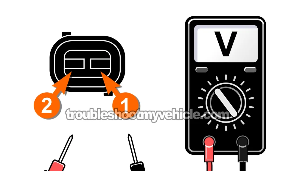
We'll perform this signal check by probing across the ECT sensor connector's two terminals with our multimeter in Volts DC mode.
If we do see these 5 Volts, it'll confirm the PCM is supplying both 5 Volts and Ground and that the wiring between the PCM and ECT sensor is OK.
NOTE: Don't have a multimeter or need to upgrade yours? This is the one I use and recommend: Tekpower TP8268 AC/DC Auto/Manual Range Digital Multimeter (at: amazon.com).
Here are the test steps:
- 1
Turn the ignition key to the ON position (engine OFF).
- 2
Unplug the ECT sensor.
- 3
Set your multimeter to Volts DC mode.
- 4
Probe the two female terminals of the ECT sensor connector (not the sensor).
Touch one multimeter lead to each terminal. - 5
You should see close to 5 Volts on the display.
Let's interpret your test result:
CASE 1: Your multimeter shows the indicate voltage. This confirms that the PCM is correctly delivering both the ECT (+) signal and ECT (-) signal.
This test result also tells us that the wiring between PCM and connector is intact (no open or shorts). Head over to: TEST 2: Check The Resistance Of The ECT Sensor.
CASE 2: Your multimeter shows 0 Volts. This generally indicates one of the following issues:
- The 5V reference wire is broken/disconnected.
- The sensor Ground path is open.
- Both circuits are compromised.
We need to troubleshoot this issue further, go to: TEST 3: Isolate Whether The 5 Volt Reference Or The Sensor Ground Is Missing.
CASE 3: You see battery voltage (12 Volts or more). This usually indicates the ECT (+) signal wire is shorted to a 12V power wire (circuit) somewhere in the engine wiring harness.
For repair tips on this type of issue, see this tutorial:
TEST 2: Check The Resistance Of The ECT Sensor
So far, you've confirmed that the ECT sensor is receiving both power and Ground from the PCM (in TEST 1). Now, it's time to test the sensor's functionality directly.
The ECT sensor is a thermistor —its electrical resistance changes in a predictable way as temperature changes:
- High resistance when cold.
- Progressively lower resistance as temperatures rise.
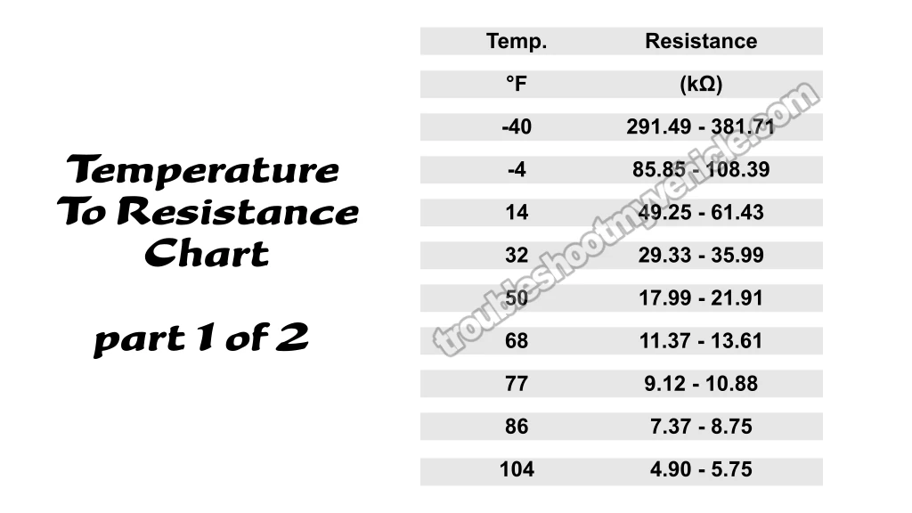
So, for this next test, you'll measure its resistance at ambient temperature and compare that reading to the manufacturer's specs (refer to the temp-to-resistance chart above).
If your Dodge Ram pickup's ECT sensor reading is within ±10°F of the actual ambient temperature, the sensor is functioning properly.
But if the reading is significantly off from the surrounding air temperature, the sensor is bad and needs to be replaced.
IMPORTANT: Engine must be completely cold (by "cold", I mean whatever ambient temp is around you). This will ensure the sensor's temperature also equals ambient air temperature.
NOTE: To test the sensor in place (on the engine), you'll need to remove the serpentine belt and unbolting the AC compressor to just set it aside. The compressor's refrigerant lines should remain connected -we're just repositioning the compressor to access the ECT sensor.
Here are the test steps:
- 1
Make sure the engine is completely cold.
By cold I mean whatever ambient temperature is around you. - 2
Disconnect the battery negative (-) terminal from the battery.
- 3
Unbolt the AC compressor and move it aside.
NOTE: DO NOT disconnect the AC compressor from its refrigerant lines. All you need to do is remove the 4 bolts that secure it to the engine and the bracket that secures it to the intake manifold. - 4
Unplug the ECT sensor.
- 5
Set your multimeter to Ohms (Ω) mode.
- 6
Measure resistance across the two terminals of the ECT sensor (not the connector, just the sensor itself).
- 7
Compare your reading to the temperature-to-resistance chart above (see the image viewer).
Your result should fall within the expected range for your current ambient temperature.
NOTE: You can use the temp your phone's weather app is reporting for your area. If you have a wall mounted thermometer, use that reading.
Let's interpret your test result:
CASE 1: The resistance reading matches the expected value for your ambient temperature (±10°F). This confirms the ECT sensor is functioning properly, since it's accurately reflecting current temperature conditions.
Let's proceed to the next diagnostic step: TEST 4: Check ECT Sensor Resistance From The PCM Connector (Wiggle Test).
CASE 2: The resistance reading is significantly higher or lower than expected and doesn't match your ambient temp. This indicates a faulty ECT sensor that's providing incorrect temperature data —which will definitely cause air/fuel mixture problems and engine performance issues.
Your next step is to replace the sensor. It's toast.


