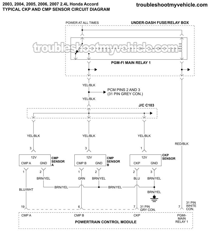
APPLIES TO: This CMP and CKP sensor circuit wiring diagram applies to the following vehicles:
- 2.4L Honda Accord (LX, EX, DX): 2003, 2004, 2005, 2006, 2007.
This CMP and CKP sensor circuit wiring diagram includes the following circuits:
- CMP Sensor A.
- Mounted on the intake camshaft and used by the VTC (Variable Timing Control) system to monitor camshaft position and adjust valve timing for engine performance and efficiency.
- CMP Sensor B.
- Mounted on the exhaust camshaft and used together with the CKP sensor to identify cylinder #1's position and synchronize fuel injection and ignition timing.
- CKP Sensor.
- Monitors crankshaft position and speed, providing the PCM with the base timing signal for engine operation.
CMP AND CKP SENSOR TESTS: The CMP (A and B) and CKP sensors can be tested with a multimeter and I'll show you how here:
- How To Test The Camshaft Position Sensor A (2003-2007 2.4L Honda Accord).
- How To Test The Camshaft Position Sensor B (2003-2007 2.4L Honda Accord).
- How To Test The Crankshaft Position Sensor (2003-2007 2.4L Honda Accord).
IGNITION COIL TESTS: Step-by-step tutorial explaining how to check the ignition coils:
ENGINE NO-START DIAGNOSTICS:
Ignition System Circuit Wiring Diagrams
More 2.4L Honda Accord Test Tutorials
You can find a complete list of 2.4L Honda Accord wiring diagrams and diagnostic tutorials in this index:
Here's a sample of the tutorials you'll find there:
- How To Test Misfire Trouble Codes (2003-2006 2.4L Honda Accord).
- How To Test The Engine Compression (2003-2006 2.4L Honda Accord).
- How To Test The Fuel Injectors (2003-2006 2.4L Honda Accord).
- How To Test The MAP Sensor (1993-1996 2.2L Buick Century, Oldsmobile Cutlass Ciera).

If this info saved the day, buy me a beer!

