

Sooner or later, the throttle position sensor (TPS) on your 3.4L V6 Oldsmobile Alero is going to fail. When it does, the check engine light will usually come on, with the usual TPS trouble codes P0121, P0122, or P0123 stored in the PCM's memory.
Thankfully, checking the TP sensor isn't difficult. All you need is a multimeter, and in this tutorial, I'm going to show you how to test it without using a scan tool.
We'll be doing three basic checks. First, we'll make sure the TP sensor is creating a throttle position signal the PCM can use. After that, we'll verify that the sensor is receiving both its 5-Volt reference signal and Ground.
I'll walk you through each test one step at a time so that, by the end of the tutorial, you'll know whether the TP sensor has failed or whether the problem is somewhere else in its electrical circuit.
Contents of this tutorial:
- Symptoms Of A Bad Throttle Position Sensor.
- Throttle Position Sensor (TPS) Circuit Descriptions.
- Where To Buy A Throttle Position Sensor And Save.
- TEST 1: Checking The TPS Voltage Signal.
- TEST 2: Making Sure The TPS Is Receiving 5 Volts.
- TEST 3: Making Sure The TPS Is Receiving Ground.
- More 3.4L V6 Oldsmobile Alero Diagnostic Tutorials.
ES  You can find this tutorial in Spanish here: Cómo Probar El TPS Con Un Multímetro (1999-2004 3.4L V6 Oldsmobile Alero) (at: autotecnico-online.com).
APPLIES TO: This tutorial applies to the following vehicles:
- 3.4L V6 Oldsmobile Alero: 1999, 2000, 2001, 2002, 2003, 2004.
Symptoms Of A Bad Throttle Position Sensor
The throttle position sensor (TPS) lets the PCM know exactly how far the throttle plate is opening and closing as you press and release the accelerator pedal. The PCM uses that information to control fuel delivery, ignition timing, transmission shifting, and several other engine management functions.
When the TP sensor fails, it sends an erratic or incorrect signal to the PCM. Once that happens, the PCM can no longer accurately determine the throttle plate's position, and that's when driveability problems begin to show up (not to mention a check engine light shining nice and bright).
If you scan the PCM's memory for trouble codes, you'll usually find one or more of the following OBD II diagnostic trouble codes:
- P0121: Throttle Position (TP) Sensor 1 Performance.
- P0122: Throttle Position (TP) Sensor 1 Circuit Low Voltage.
- P0123: Throttle Position (TP) Sensor 1 Circuit High Voltage.
- P1121: TP Sensor Inconsistent With MAP Sensor.
Depending on how the TP sensor has failed, you might notice one or more of the following symptoms:
- Engine hesitation: The engine hesitates or stumbles when you step on the accelerator.
- Poor acceleration: The engine doesn't accelerate as well as it should.
- Bad gas mileage: Fuel mileage drops noticeably.
- High or low idle speed: The engine idles either too high or too low.
- Rough idle: The engine runs rough while idling.
- Starts then stalls: The engine starts but stalls almost immediately.
- Engine cranks but doesn't start: The engine cranks normally but won't start.
Throttle Position Sensor (TPS) Circuit Descriptions
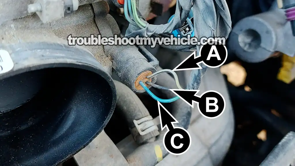
Before we start testing the throttle position sensor, it's a good idea to know what each of its three wires does.
Each wire has a specific job. One carries the TP signal back to the PCM, another supplies power to the sensor, and the third provides Ground.
The table below gives you a brief description of each circuit:
| Terminal | Wire | Description |
|---|---|---|
| A | Gray (GRY) | 5 Volts (1994-2000) |
| Gray with black stripe (GRY/BLK) | 5 Volts (2001-2005) | |
| B | Black (BLK) | Sensor Ground |
| C | Dark Blue (DK BLU) | TPS Signal |
Where To Buy A Throttle Position Sensor And Save
If you end up needing a new throttle position sensor, the links below let you compare prices from a couple of well-known automotive brands. These are quality, direct-fit replacement sensors made for the 1999-2004 3.4L V6 Oldsmobile Alero, not the cheap no-name parts that sometimes don't last very long.


Disclosure: As an Amazon Associate, I earn from qualifying purchases. If my tutorials help you, using these links is an easy way to support the site at no extra cost to you. Thank you!
TEST 1: Checking The TPS Voltage Signal
Our first test is gonna verify that the throttle position sensor is creating the correct voltage signal as the throttle plate opens and closes.
When a TP sensor is functioning correctly, its signal voltage looks like this:
- Throttle plate closed: The TP signal voltage should be about 0.4 to 0.9 Volts DC.
- Wide-open throttle (WOT): The TP signal voltage should increase smoothly to about 4.5 to 5.0 Volts DC.
A TP sensor that's toast, it's signal voltage will do one of two things:
- The signal voltage stays fixed: The TP signal stays at the same voltage no matter how far the throttle plate is opened.
- The signal voltage glitches: The TP signal suddenly drops out, jumps around, or skips as you slowly open and close the throttle plate.
To check the TP signal, we're going to measure the voltage on the dark blue (DK BLU) wire at the TP sensor's 3-wire connector.
The DK BLU wire connects to the female terminal identified by the letter C in the photo above.
IMPORTANT: The TP sensor must remain connected to its electrical connector during this test. The easiest way to access the signal wire is with a wire-piercing probe or a back-probe. You can see what these tools look like and where to buy them here: Goupchn 4mm Banana to Banana Plug Test Leads Kit (Amazon affiliate link).
Let's get started:
- 1
Set your multimeter to Volts DC mode.
- 2
Connect the black multimeter lead directly to the battery negative (-) terminal.
- 3
Turn the ignition key to the ON position, but don't crank or start the engine.
- 4
Probe the dark blue (DK BLU) wire with the red multimeter lead.
The DK BLU wire connects to terminal C of the TP sensor connector.
NOTE: The TP sensor must remain plugged into its connector while you're testing the signal voltage. - 5
Manually open the throttle plate.
You'll get more accurate results by opening and closing the throttle plate directly at the throttle body instead of pressing the accelerator pedal. - 6
With the throttle plate fully closed, your multimeter should register approximately 0.4 to 0.9 Volts DC.
- 7
Slowly open the throttle plate.
The voltage should increase smoothly without any sudden jumps or dropouts.
At wide-open throttle, you should see about 4.5 to 5.0 Volts DC. - 8
Slowly close the throttle plate while watching the multimeter.
The voltage should decrease smoothly and return to approximately the same value you observed in STEP 6. - 9
Lightly tap the TP sensor with the plastic handle of a screwdriver while slowly opening and closing the throttle plate.
A good TP sensor will continue producing a smooth, uninterrupted voltage signal. If the voltage suddenly drops out, jumps, or skips while tapping the sensor, the sensor is defective.
Now let's take a look at what your test results mean:
CASE 1: The TP sensor voltage increased and decreased smoothly as the throttle plate was opened and closed. That's exactly what you want to see. It confirms that the throttle position sensor is working properly.
It also confirms that the sensor is receiving both its 5-Volt reference signal and Ground from the PCM.
CASE 2: The TP sensor voltage stayed fixed as the throttle plate was opened and closed. This usually means the throttle position sensor has failed. Before replacing it, though, we've got to make sure it's receiving both its 5-Volt reference signal and Ground.
Our next step is to verify that the GRY (or GRY/BLK) wire is supplying the sensor with its 5-Volt reference signal. Head over to: TEST 2: Making Sure The TPS Is Receiving 5 Volts.
CASE 3: The multimeter didn't register a TP sensor voltage signal. This usually means there's a problem with the TP sensor itself or with one of its electrical circuits.
Before we condemn the sensor, we've got to verify that the GRY (or GRY/BLK) wire is supplying it with the 5-Volt reference signal from the PCM. For that test, head over to: TEST 2: Making Sure The TPS Is Receiving 5 Volts.
TEST 2: Making Sure The TPS Is Receiving 5 Volts
As I mentioned earlier, the throttle position sensor can't do its job unless it's receiving two things: a 5 Volts and Ground (both of which are supplied by the PCM).
In this test, we're going to make sure the PCM is supplying the sensor with that 5-Volt reference signal. On the 1999-2004 3.4L V6 Oldsmobile Alero, that voltage is carried on the gray (GRY) wire.
The GRY wire connects to the female terminal identified by the letter A in the illustration above.
One important thing to keep in mind is that the PCM only supplies this 5-Volt reference signal when the ignition switch is in the ON or START position. So, for this test, leave the engine OFF and turn the ignition key to the ON position.
Let's get started:
- 1
Unplug the throttle position sensor from its electrical connector.
- 2
Set your multimeter to Volts DC mode.
- 3
Connect the black multimeter lead directly to the battery negative (-) terminal.
- 4
Turn the ignition key to the ON position, but don't crank or start the engine.
- 5
Probe terminal A with the red multimeter lead.
Terminal A is the female terminal connected to the GRY or GRY/BLK wire. - 6
Your multimeter should register approximately 5 Volts DC (about 4.5 to 5.0 Volts).
Now let's take a look at what your test results mean:
CASE 1: The GRY wire is supplying 5 Volts. That's exactly what you want to see. It confirms that the PCM is supplying the throttle position sensor with the 5 Volts it needs to function.
Now that we've confirmed the sensor is receiving 5 Volts, our next step is to make sure it's getting a good Ground. Head over to: TEST 3: Making Sure The TPS Is Receiving Ground.
CASE 2: The GRY wire isn't supplying 5 Volts. Without this 5-Volt reference signal, the throttle position sensor can't generate a throttle position signal.
In most cases, this is caused by an open-circuit problem in the GRY wire somewhere between the TPS connector and the PCM connector. Although it's possible that the PCM itself has failed, that's much less common.
Your next step is to find and repair the cause of the missing 5-Volt reference signal. Once you've restored that voltage, the throttle position sensor will be able to operate normally.
TEST 3: Making Sure The TPS Is Receiving Ground
So far, our test results have already told us two important things:
- TEST 1: The TP sensor voltage signal didn't respond correctly as the throttle plate was opened and closed.
- TEST 2: The TP sensor is getting 5 Volts.
We've got one last circuit to check. We need to make sure the black (BLK) wire, which connects to terminal B, is providing the throttle position sensor with a good Ground.
Just like the 5-Volt reference signal, this Ground is only available when the ignition switch is in the ON or START position. So, for this test, turn the ignition key to the ON position, but leave the engine OFF.
IMPORTANT: Don't apply battery voltage directly to the Ground circuit. Doing so will damage the PCM. The multimeter test outlined below is the safe way to verify that the Ground circuit is working properly.
Let's get started:
- 1
Disconnect the throttle position sensor from its electrical connector.
- 2
Set your multimeter to Volts DC mode.
- 3
Connect the red multimeter lead directly to the battery positive (+) terminal.
- 4
Turn the ignition key to the ON position, but don't crank or start the engine.
- 5
Probe terminal B with the black multimeter lead.
Terminal B is connected to the BLK wire. - 6
Your multimeter should register about 10 to 12 Volts DC.
Now let's interpret your test results:
CASE 1: The BLK wire is providing a good Ground. That's exactly what we were hoping to find.
At this point, if your test results match all three conditions below, you can confidently replace the throttle position sensor:
- TEST 1: The TP sensor voltage signal didn't respond smoothly as the throttle plate was opened and closed.
- TEST 2: The sensor is receiving its 5-Volt reference signal.
- TEST 3: The sensor is receiving a good Ground.
CASE 2: The BLK wire isn't providing Ground. Without a good Ground, the throttle position sensor can't create a throttle position signal for the PCM.
In most cases, the problem is an open-circuit issue in the BLK wire somewhere between the TPS connector and the PCM connector. Although it's possible the PCM is at fault, that's much less common.
Your next step is to find and repair the open in the Ground circuit. Once the Ground has been restored, the throttle position sensor will be able to operate normally.
More 3.4L V6 Oldsmobile Alero Diagnostic Tutorials
You can find a complete list of diagnostic tutorials for the 3.4L V6 Oldsmobile Alero in this index:
Here's a sample of the tutorials you'll find there:
- How To Test Engine Compression (1999-2004 3.4L V6 Oldsmobile Alero).
- How To Test For A Blown Head Gasket (1999-2004 3.4L V6 Olds Alero).
- Common Causes Of Spark Plug Failure (1999-2004 3.4L V6 Olds Alero).
- How To Test The 7X Crankshaft Position Sensor (1994-2004 3.4L V6 Olds Alero).

If this info saved the day, buy me a beer!
