

The 7X crankshaft position (CKP) sensor plays a critical role in starting and keeping your 1999-2004 3.4L V6 Oldsmobile Alero running. If it stops generating its 7X CKP signal, the ignition control module (ICM) and the fuel injection system no longer know when to fire the ignition coils and fuel injectors. The end result is an engine no-start.
Fortunately, checking the 7X CKP sensor isn't complicated. In this tutorial, I'll show you how to test it step by step using nothing more than a multimeter. No scan tool (or any special diagnostic equipment) required.
Contents of this tutorial:
APPLIES TO: This tutorial applies to the following vehicles:
- 3.4L V6 Oldsmobile Alero: 1999, 2000, 2001, 2002, 2003, 2004.
Symptoms Of A Bad 7X CKP Sensor
The 7X CKP sensor generates the crankshaft position signal that the ignition control module (ICM) needs to know when to fire the ignition coils. The ICM also uses this signal to calculate engine speed and send that information to the PCM.
If the 7X CKP sensor stops generating its signal, the ignition control module no longer knows when to fire the ignition coils. The result is that the ignition system stops producing spark, and the engine will crank but won't start.
One thing to keep in mind is that a failed 7X CKP sensor usually doesn't set its own diagnostic trouble code. In most cases, all you'll notice is that the engine cranks normally but refuses to start.
Here are the most common symptoms you'll see when the 7X CKP sensor fails:
- Engine cranks but won't start: This is by far the most common symptom of a failed 7X CKP sensor.
- No spark: None of the ignition coils will produce spark while the engine is cranking.
- Intermittent stalling: If the sensor signal cuts out while the engine is running, the engine may stall unexpectedly.
Circuit Description Of The 7X CKP Sensor
The 7X CKP sensor is a two-wire magnetic pickup sensor, also known as a variable reluctance sensor. Unlike a Hall-effect sensor, it doesn't need a power supply or Ground to produce its signal.
As the crankshaft rotates, the reluctor wheel passes by the tip of the sensor. This changing magnetic field causes the sensor to generate its own alternating current (AC) voltage signal. As engine speed increases, both the frequency and the voltage of that AC signal increase.
The sensor's AC signal travels through two wires directly to the ignition control module (ICM). The ICM uses this information to determine crankshaft position and engine speed so it knows when to fire the ignition coils.
The 7X CKP sensor is a 2-wire sensor with male spade terminals. The engine wiring harness (that connects to it) has corresponding female terminals.
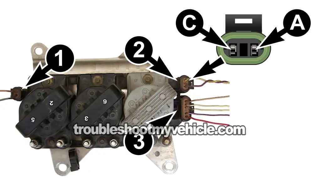
The table below identifies the two wires of the 7X CKP sensor connector at ignition control module connector 2.
| 1999-2004 7X CKP Sensor Connector | ||
|---|---|---|
| Pin | Wire Color | Description |
| A | Yellow (YEL) | CKP Signal High |
| C | Purple (PPL) | CKP Signal Low |
Where To Buy The 7X CKP Sensor
If your testing confirms that the 7X crankshaft position sensor has failed, I recommend replacing it with a quality sensor from either ACDelco or Standard Motor Products —both with an excellent reputation for producing reliable replacement parts.
You can compare prices and availability by checking out the links below:


TEST 1: Testing The 7X CKP Sensor Signal
Our first test is going to check whether the 7X CKP sensor is generating an AC voltage signal while the engine is cranking. We'll use a multimeter set to AC Volts to measure this signal.
We'll perform the test at the ignition control module by disconnecting connector 2 (see the image above). This connector has two wires: a yellow (YEL) wire and a purple (PPL) wire.
Before you begin, make sure the battery is fully charged. A weak battery can reduce cranking speed and affect the AC voltage produced by the sensor.
NOTE: This test only applies to an engine that cranks but doesn't start. If the engine starts and runs, the 7X CKP sensor is already producing its signal.
CAUTION: You'll be working around a cranking engine. Stay clear of all moving parts and follow all necessary safety precautions.
Follow these steps:
- 1
Set your multimeter to AC Volts.
- 2
Disconnect connector 2 from the ignition control module.
- 3
Connect the red multimeter lead to the wire connected to terminal A.
- 4
Connect the black multimeter lead to the wire connected to terminal C.
- 5
Have an assistant crank the engine while you observe the multimeter.
- 6
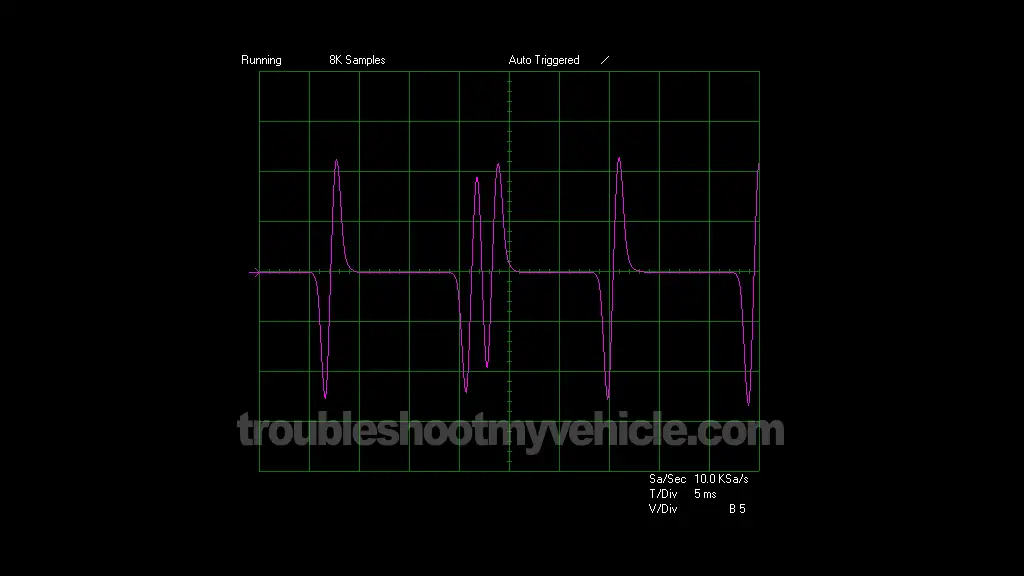
The AC voltage should fluctuate continuously between about 0.3 and 1.0 Volts AC while the engine is cranking.
The exact voltage you see will vary depending on how fast the engine is cranking. A fully charged battery usually produces the highest AC voltage reading.
If you're using an oscilloscope instead of a multimeter, the waveform should match the one shown in image 2 of 2 in the image viewer above.
Let's take a look at what your test results mean:
CASE 1: Your multimeter registered an AC voltage signal. That's exactly what you want to see. It confirms that the 7X CKP sensor is generating its crankshaft position signal.
If you're troubleshooting an engine that cranks but won't start because there's no spark, this result usually points to a failed ignition control module (ICM).
Before replacing the ignition control module, I recommend performing one more test. The next step is to check the resistance of the 7X CKP sensor. Go to: TEST 2: 7X CKP Sensor Resistance Test.
CASE 2: Your multimeter didn't register an AC voltage signal. Before assuming the sensor has failed, double-check your meter connections and repeat the test.
If the multimeter still doesn't register an AC voltage signal while the engine is cranking, don't replace the sensor just yet. One of the most common causes of this problem is a damaged wiring harness between the sensor and the ignition control module.
IMPORTANT: Before replacing the sensor, inspect the wiring harness carefully. The two sensor wires pass underneath the rear exhaust manifold, where heat and vibration can damage the insulation. Here's what usually happens:
- The wiring harness is held in place by retaining clips that can become brittle or break with age.
- Once the harness comes loose, it can rub against the engine or rest against the hot exhaust manifold.
- Eventually, the insulation wears through or melts, allowing one or both wires to short to Ground.
- When that happens, the AC signal generated by the 7X CKP sensor never reaches the ignition control module.
So, if you didn't get an AC voltage reading in this test, inspect the wiring before replacing the sensor. If you find damaged wiring, repairing it may solve the problem and save you the cost of a new crankshaft position sensor.
If the harness is damaged, you have a couple of repair options:
- Repair the damaged section of the existing wiring harness.
- Replace the harness with a good used one from a salvage yard.
TEST 2: Checking The 7X CKP Sensor's Resistance
In most cases, if the 7X CKP sensor generated an AC voltage signal in TEST 1, you can safely conclude that it's working properly and that the ignition control module (ICM) is causing the no-spark condition.
Even so, I recommend performing one last test before replacing the ignition control module. We'll measure the internal resistance of the 7X CKP sensor to make sure it isn't failing internally.
Since the sensor is mounted in a difficult-to-reach location on the engine, we'll check its resistance at connector 2 of the ignition control module. This allows us to test the sensor without removing it or disconnecting it from the engine.
NOTE: This resistance test is performed on the female terminals of the ignition control module's connector 2.
Here's what you need to do:
- 1
Put your multimeter in Ohms (Ω) mode.
- 2
Disconnect Connector 2 from the ignition control module.
- 3
Connect the red multimeter test lead to female terminal A.
- 4
Connect the black multimeter test lead to female terminal C.
- 5
The multimeter's Ohms reading should read 500 to 900 Ohms.
Now let's see what your test results mean:
CASE 1: Your multimeter showed the specified resistance. That's the correct test result. It confirms that the 7X CKP sensor's internal winding is within specification.
If you've also confirmed that the sensor is producing an AC voltage signal during TEST 1, then you can confidently rule out the 7X CKP sensor as the cause of the no-start or no-spark condition.
At this point, if the ignition system still isn't producing spark, the ignition control module (ICM) is the most likely cause of the problem.
CASE 2: Your multimeter didn't show the specified resistance. Before condemning the sensor, double-check your meter connections and repeat the test.
If the resistance is still outside the specified range, you can conclude that the 7X CKP sensor has failed internally and needs to be replaced.
As with the previous test, don't forget to inspect the wiring harness before replacing the sensor. A damaged harness can cause symptoms that closely resemble a failed crankshaft position sensor.
More 3.4L V6 Oldsmobile Alero Diagnostic Tutorials
You can find a complete list of diagnostics tutorials for your 3.4L V6 Oldsmobile Alero in this index:
Here's a small sample of the tutorials you'll find:
- How To Test The TPS With A Multimeter (1999-2004 3.4L V6 Oldsmobile Alero).
- How To Test For A Blown Head Gasket (1999-2004 3.4L V6 Olds Alero).
- Common Causes Of Spark Plug Failure (1999-2004 3.4L V6 Olds Alero).
- How To Test Engine Compression (1999-2004 3.4L V6 Oldsmobile Alero).

If this info saved the day, buy me a beer!
