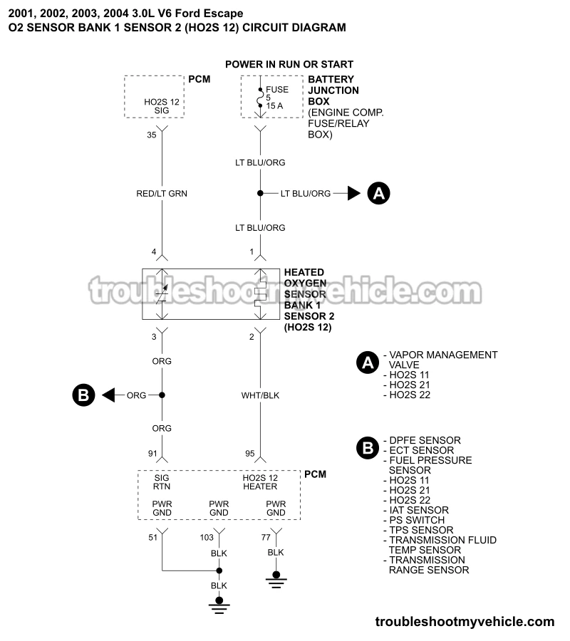
APPLIES TO: This Bank 1 Sensor 2 O2 sensor circuit wiring diagram applies to the following vehicles:
- 3.0L V6 Ford Escape: 2001, 2002, 2003, 2004.
This wiring diagram includes the following circuits:
-
Fuse 5: Located in the Battery Junction Box, front left corner of engine compartment.
-
Heated Oxygen Sensor Bank 1 Sensor 2 (HO2S 12): Located on the Y exhaust pipe that connects to the exhaust manifold facing the firewall.
Monitors the efficiency and performance of the catalytic converter that scrubs the exhaust gas of cylinders 1, 2, and 3 (Bank 1).
HO2S Bank 1 Sensor 2 Connector Pinout

| Pin | Wire | Description |
|---|---|---|
| 1 | Light blue with orange stripe (LT BLU/ORG) | VPWR –Vehicle Power (12 Volts) |
| 2 | White with black stripe (WHT/BLK) | HO2S 12 HEATER –PCM Supplied Ground (heater activation signal) |
| 3 | Orange (ORG) | SIG RTN –O2 Sensor Signal Ground |
| 4 | Gray with light blue stripe (GRY/LT BLU) | HO2S 12 SIG –O2 Sensor Signal |
P0141 DIAGNOSTIC TESTS: The following tutorial will help you test the heater element of the H2OS 12 sensor with a multimeter:
Related O2 Sensor Circuit Wiring Diagrams
- O2 Sensor Bank 1 Sensor 1 Circuit Wiring Diagram (2001-2004 3.0L V6 Ford Escape).
- O2 Sensor Bank 2 Sensor 1 Circuit Wiring Diagram (2001-2004 3.0L V6 Ford Escape).
- O2 Sensor Bank 2 Sensor 2 Circuit Wiring Diagram (2001-2004 3.0L V6 Ford Escape).
More 3.0L V6 Ford Escape Wiring Diagrams And Tutorials
You can find a complete list of wiring diagrams and diagnostic test tutorials here:
Here's a sample of the tutorials you'll find there:
- How To Test The Fuel Injectors (2001-2004 3.0L Ford Escape).
- How To Test The Ignition COP Coils (2001-2007 3.0L V6 Ford Escape).
- How To Test The Cooling Fan Motors (2001-2004 3.0L V6 Ford Escape - Mazda Tribute).
- How To Test For A Blown Head Gasket (2001-2012 3.0L V6 Ford Escape, Mercury Mariner).

If this info saved the day, buy me a beer!

