Page 2 of 2
1995 PCM BLUE Connector

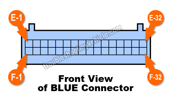
One row of the BLUE PCM's connector is prefixed with the letter E and its 16 terminals are labeled E-1 thru' E-16. The other row is prefixed with the letter F and its 16 terminals are labeled F-1 thru' F-16 (see the illustration above).
| BLUE PCM 32 Pin Connector | ||
|---|---|---|
| Pin | Wire Color | Description |
| E-1 | GRY | EGR Solenoid |
| E-2 | WHT | 3-2 Shift Control Solenoid |
| E-3 | --- | Empty |
| E-4 | DK BLU | Range Signal B |
| E-5 | RED | Range Signal C |
| E-6 | BRN/WHT | Check Engine Light (CEL) |
| E-7 | --- | Not Used |
| E-8 | YEL/BLK | 2-3 Shift Solenoid Enable |
| E-9 | LT GRN | 1-2 Shift Solenoid Enable |
| E-10 | TAN/BLK | TCC Solenoid (w/ 4L60-E Only) |
| E-11 | BRN | TCC Solenoid (w/ 4L60-E Only) |
| E-12 | DK GRN | A/C Request |
| E-13 | PPL | Brake Switch |
| E-14 | GRY | 5 Volt Ref (MAP, Linear EGR) |
| E-15 | PNK | IGN Fused |
| E-16 | ORN | Battery Feed |
| F-1 | PNK | Range Signal A |
| F-2 | RED/BLK | Trans Input Shaft Speed Sensor (+) |
| F-3 | DK BLU/WHT | Trans Input Shaft Speed Sensor (-) |
| F-4 | --- | Empty |
| F-5 | --- | Empty |
| F-6 | DK GRN/WHT | Fuel Pump Relay Control |
| F-7 | LT BLU/WHT | Pressure Control Solenoid 'Low' |
| F-8 | GRY/BLK | 4WD Switch |
| F-9 | TAN | Serial Data |
| F-10 | RED/BLK | Pressure Control Solenoid 'Hi' |
| F-11 | WHT | Ignition Control Module Signal |
| F-12 | BRN | Transmission Output Speed |
| F-13 | DK BLU | VSS Signal |
| F-14 | GRY | 5 Volt Sensor Reference Voltage (TPS, MAP) |
| F-15 | PNK | IGN Feed |
| F-16 | DK GRN/WHT | Canister Purge Solenoid |

Safety Precautions
Here are some very important safety precautions when testing the wires coming out of the PCM connectors.
- If one or any of the wires on your GM vehicle DO NOT match the color stated in the pin out charts, then you should not use the pin out charts in this article. Why? Because this is the clearest indication that these ARE NOT the connector pin out charts for your particular vehicle.
- Never probe the front of the connector.
- You should use a wire piercing probe and probe the wire a few inches away from the connector.
- To see what this tool looks like: Wire Piercing Probe.
- You should use a back probe.
- You should use a wire piercing probe and probe the wire a few inches away from the connector.
- Read the Disclaimer.

If this info saved the day, buy me a beer!

