TEST 2: Using A Jumper Wire To Bypass The Blower Switch
The tests in this section are designed to let you know if there's a problem with the wiring or the components (e.g. blower resistor and blower relay) between the blower switch connector and the blower motor.
The results of this test come in handy if the blower control switch is OK (either because you have tested it or you've already replaced it with a new one).
We'll accomplish these tests by using a jumper wire and bypassing the blower switch circuits indicated in the steps below.
As you bypass each blower speed, the blower motor should run if everything is OK.
IMPORTANT: The jumper wire you use must be of a small enough diameter (gauge) so that the blower motor switch connector's female metal terminals aren't damaged. If you use a too thick jumper wire, you may permanently open these terminals up and create an intermittent 'open' problem.
Alright, these are the test steps:
- 1
Disconnect the blower motor switch from its harness connector and turn the key to the on position (but no need to start the engine).
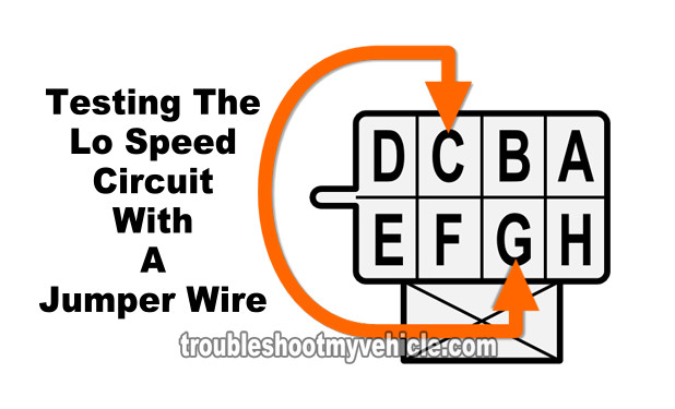
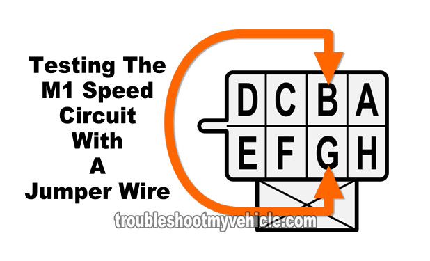
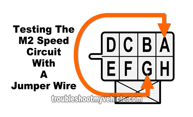
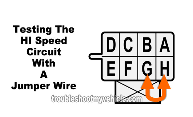
NOTE: All of the tests in this section are done on the blower switch's harness connector and not on the switch itself. The illustrations in the image viewer show the front view of the female metal terminals of the connector. - 2
Jumper terminals C and G together. This is the circuit that controls blower speed LO.
The correct test result is for the blower motor to run on LO speed. - 3
Jumper terminals B and G together. This is the circuit that controls blower speed M1.
The correct test result is for the blower motor to run on M1 speed. - 4
Jumper terminals A and G together. This is the circuit that controls blower speed M2.
The correct test result is for the blower motor to run on M2 speed. - 5
Jumper terminals H and G together. This is the circuit that controls blower speed HI.
The correct test result is for the blower motor to run on HI speed.
Let's take a look at what your test results mean:
CASE 1: The blower motor DID NOT run when two or all of the indicated terminals were jumpered. This tells you that that specific circuit is bad.
Although it's beyond the scope of this tutorial to test these circuits, you have eliminated the blower switch (on the A/C-Heater control panel) as bad. There's a good chance that you've got a bad blower motor resistor. The blower motor resistor can be tested and you can find the tutorial here:
CASE 2: The blower motor ran when all of the indicated terminals were jumpered together. This tells you several important things:
- That the circuits between the resistor connector and the blower motor are OK.
- That the blower motor relay is OK.
No further testing is required of the blower resistor, the blower relay or the blower motor.
Related Test Articles
If you enjoyed and/or found this 'How to' article helpful, I have written several more 4.3L, 5.0L, 5.7L specific test articles. You can find them all in this index: GM 4.3L, 5.0L, 5.7L Index of Articles
Here's a small sample of the articles you'll find there:
- How To Troubleshoot A No Start (GM 4.3L, 5.0L, 5.7L).
- How To Test The 'Spider' Fuel Injector Assembly (4.3L, 5.0L, 5.7L).
- How To Test The Engine Compression (GM 4.3L, 5.0L, 5.7L).
- How To Test The Crank Sensor (GM 4.3L, 5.0L, 5.7L).
- How To Test The GM MAF Sensor 3.1L, 3.4L, 4.3L, 5.0L and 5.7L (at: easyautodiagnostics.com).
- How To Test A Misfire / No Spark-No Start Condition (4.3L, 5.0L, 5.7L 96-04) (at: easyautodiagnostics.com).

If this info saved the day, buy me a beer!


