")
This tutorial will explain how to test the electronic throttle body on the 2002-2007 4.2L Chevrolet TrailBlazer and GMC Envoy.
You'll be able to find out if TPS 1 or TPS 2 is defective or not. We'll also test the throttle actuator motor.
You don't need any expensive diagnostic equipment to test the electronic throttle body since I'll show you how to resistance-test the throttle position sensors and the throttle actuator motor using a multimeter.
Contents of this tutorial:
- Symptoms Of A Bad Electronic Throttle Body.
- Electronic Throttle Body Terminal Pin Out Chart.
- Where To Buy The Electronic Throttle Body And Save.
- TEST 1: TPS 1 Resistance Test (Part 1 Of 2).
- TEST 2: TPS 1 Resistance Test (Part 2 Of 2).
- TEST 3: TPS 2 Resistance Test (Part 1 Of 2).
- TEST 4: TPS 2 Resistance Test (Part 2 Of 2).
- TEST 5: Testing The TAC Motor.
- More GM 4.2L Test Tutorials.
ES ![]() You can find this tutorial in Spanish here: Cómo Probar El Cuerpo Del Acelerador Electrónico (2002-2007 4.2L Chevrolet TrailBlazer) (at: autotecnico-online.com).
You can find this tutorial in Spanish here: Cómo Probar El Cuerpo Del Acelerador Electrónico (2002-2007 4.2L Chevrolet TrailBlazer) (at: autotecnico-online.com).
APPLIES TO: This tutorial applies to the following vehicles:
- 4.2L Chevrolet TrailBlazer: 2002, 2003, 2004, 2005, 2006, 2007.
- 4.2L GMC Envoy: 2002, 2003, 2004, 2005, 2006, 2007.
WIRING DIAGRAMS: You can find the TAC system wiring diagram here:
- TAC System Wiring Diagram (2002-2005 4.2L Chevrolet TrailBlazer).
- TAC System Wiring Diagram (2006-2007 4.2L Chevrolet TrailBlazer).
If you need to test the APP sensor assembly (2002-2003 TrailBlazer and Envoy only), you can find the tutorial here: How To Test APP Sensor 1 And 2 (2002-2003 4.2L Chevrolet TrailBlazer).
Symptoms Of A Bad Electronic Throttle Body
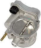
As you're probably already aware, the electronic throttle body comprises three components. These are TPS 1, TPS 2, and the throttle actuator motor (for the sake of our testing discussion, I'm leaving out the throttle plate).
The throttle position sensors within the throttle body are tasked with informing the fuel injection computer of the throttle plate angle.
Since the electronic throttle body is a critical component of the engine's management system, when one of its throttle position sensors fails, you'll see one or more of the following trouble codes:
- P0121: Throttle Position Sensor (TPS) Sensor 1 Performance.
- P0122: Throttle Position Sensor (TPS) Sensor 1 Circuit Low Voltage.
- P0123: Throttle Position Sensor (TPS) Sensor 1 Circuit High Voltage.
- P0222: Throttle Position Sensor (TPS) Sensor 2 Circuit Low Voltage.
- P0223: Throttle Position Sensor (TPS) Sensor 2 Circuit High Voltage.
- P2135: Throttle Position Sensor (TPS) Sensor 1 And 2 Correlation.
You'll also see one or more of the following symptoms:
- Your Chevy TrailBlazer or GMC Envoy will run in Reduced Engine Power mode.
- The engine starts and runs but when you try to accelerate your Chevy TrailBlazer or GMC Envoy, it accelerates very slowly.
- The engine starts and runs but the engine does not accelerate when you step on the accelerator pedal.
- The engine starts and runs but shuts down.
Electronic Throttle Body Terminal Pin Out Chart
")
| Pin | Wire Color | Description |
|---|---|---|
| A | Dark green (DK GRN) | TPS 1 Signal |
| B | Light blue with black stripe (LT BLU/BLK) | 5 Volts (TPS 2) |
| C | Black (BLK) | Ground (TPS 1) |
| D | Purple (PPL) | TPS 2 Signal |
| E | Yellow (YEL) | Throttle Actuator Motor Control |
| F | Brown (BRN) | Throttle Actuator Motor Control |
| G | Grey (GRY) | 5 Volts (TPS 1) |
| H | Black with white stripe (BLK/WHT) | Ground (TPS 2) |
The connector on the throttle body itself has male spade terminals. The terminals on the electrical connector are female terminals.
You'll perform all of the tests (in this tutorial) on the connector of the throttle body itself, and this connector has male spade terminals.
Where To Buy The Electronic Throttle Body And Save
The following links will help you comparison shop for the electronic throttle body for the 2003, 2004, 2005, 2006, and 2007 4.2L Chevrolet TrailBlazer Or 4.2L GMC Envoy:

Disclosure: As an Amazon Associate, I earn from qualifying purchases. If my tutorials help you, using these links is an easy way to support the site at no extra cost to you. Thank you!
Not sure if the electronic throttle body will fit your particular GM vehicle? Don't worry, once you get to the site, they'll make sure it fits. If it doesn't, they'll find you the right one.
TEST 1: TPS 1 Resistance Test (Part 1 Of 2)
")
Testing the throttle position sensors within the electronic throttle body involves testing the resistance between two terminals.
For our first test, we'll test the resistance of terminal C and terminal G of TPS 1.
Terminal C is the terminal that receives Ground from your Chevy Trailblazer or GMC Envoy's fuel injection computer.
Terminal G is the terminal that receives 5 Volts from the fuel injection computer.
We're looking to make sure that this circuit hasn't suffered an open-circuit or short-circuit problem.
If there's an open-circuit problem between them, your multimeter will not register continuity in this circuit. If you're using a digital multimeter, you'll see the letters OL displayed on your multimeter's screen.
If there's a short-circuit problem between them, you'll see an Ohm reading of less than 1 Ohm on your multimeter.
NOTE: All multimeter connections are done on the male spade terminals of the electronic throttle body itself.
TIP: The easiest way that I've found to test the resistance between the terminals is to connect the multimeter test leads to the terminals with jumper wires that have alligator clips on both ends (see photo 2 of 2 in the image viewer above). Need to buy some? Jumper Wires With Insulated Alligator Clips (Amazon affiliate link).
These are the test steps:
- 1
Disconnect the throttle body from its electrical connector.
- 2
Place your multimeter in Ohms mode.
- 3
Connect the red multimeter test lead to terminal C.
- 4
Connect the black multimeter test lead to terminal G.
- 5
Your multimeter should read continuity.
At this point I have gotten about 3 K Ohms from a good TPS 1.
Let's examine your test results:
CASE 1: The multimeter registered continuity between terminals C and G. This is the correct test result.
So far so good. The next test is to test the resistance between terminals A and G as you open and close the throttle plate: TEST 2: TPS 1 Resistance Test (Part 2 Of 2).
CASE 2: The multimeter registered 0 Ohms (or a value very close to it) between terminals C and G. This test result indicates that circuits C and G have a short-circuit problem.
With this test result, you can conclude that the electronic throttle body is defective and needs replacement.
CASE 3: The multimeter reports no continuity between terminals C and G (the letters OL are displayed). This test result indicates that circuits C and G have an open-circuit problem.
With this test result, you can conclude that the electronic throttle body is defective and needs replacement.
TEST 2: TPS 1 Resistance Test (Part 2 Of 2)
. How To Test The Electronic Throttle Body (2002, 2003, 2004, 2005, 2006, 2007 4.2L Chevrolet TrailBlazer Or 4.2L GMC Envoy)")
In this test section, we'll test the resistance between terminal A and terminal G as we open and close the throttle plate.
If everything is OK between these two terminals, you should see the resistance value increase as you open the throttle plate.
As you close the throttle plate, the resistance value should decrease.
Also, the resistance values should increase/decrease as you open/close the throttle plate without any gaps in the reading.
If TPS 1 is defective, you'll see that the resistance reading does not increase as you open/close the throttle plate or see gaps in the reading as you open/close the throttle plate.
These are the test steps:
- 1
Disconnect the throttle body from its electrical connector.
- 2
Place your multimeter in Ohms mode.
- 3
Connect one multimeter test lead to terminal A.
NOTE: All connection are done on the male terminals of the connector of the throttle body itself. - 4
Connect the other multimeter test lead to terminal G.
At this point I usually get a reading between 2K to 3K Ohms from a good TPS 1. - 5
Slowly open the throttle plate by hand till it reaches its wide-open throttle (WOT) position.
- 6
The resistance value should increase as you open the throttle plate.
At WOT I usually see a reading between 4K to 5K Ohms from a good TPS 1. - 7
Slowly close the throttle plate to its closed position.
- 8
The resistance value should decrease as you close the throttle plate.
- 9
Gently push down and completely close the throttle plate.
- 10
The resistance value should continue to decrease as you completely close the throttle plate.
At this point (the throttle plate pushed down and completely closed) I generally get a reading between 1K to 2K Ohms from a good TPS 1.
Let's examine your test results:
CASE 1: The resistance increased/decreased without any gaps. This is the correct test result and it lets you know that TPS 1 is OK (not defective).
The next test is to test the resistance of terminals H and B of TPS 2. Go to: TEST 3: TPS 2 Resistance Test (Part 1 Of 2).
CASE 2: The multimeter DID NOT register the indicated resistance values. This lets you know that TPS 1 is bad. You'll need to replace the throttle body unit.
TEST 3: TPS 2 Resistance Test (Part 1 Of 2)
Testing TPS 2 follows pretty much the same procedure as testing TPS 1. The difference is that we'll perform our resistance test on different terminals.
To get our TPS 2 troubleshooting test on the way, we'll test the resistance between terminal B and terminal H.
Terminal B receives Ground, and terminal H receives 5 Volts. Both Ground and the 5 Volts come from the fuel injection computer.
If everything is OK between these two terminals, you'll see a continuity reading on your multimeter.
If there's a problem between these two terminals, you'll see a reading that indicates either a short-circuit or open-circuit problem.
If there's an open-circuit problem, you'll see a no-continuity reading from your multimeter. If there's a short-circuit problem, you'll see a resistance reading of less than 1 Ohm on your multimeter.
NOTE: All tests are done on the connector on the throttle body itself. This connector has male spade terminals.
These are the test steps:
- 1
Disconnect the throttle body from its electrical connector.
- 2
Place your multimeter in Ohms mode.
- 3
Connect the red multimeter test lead to terminal B.
- 4
Connect the black multimeter test lead to terminal H.
- 5
Your multimeter should read continuity.
At this point I have gotten around 2K Ohms from a good TPS 2.
Let's examine your test results:
CASE 1: The multimeter registered continuity between terminals B and H. This is the correct test result.
The next step is to test TPS 2 while you open and close the throttle plate. For this test go to: TEST 4: TPS 2 Resistance Test (Part 2 Of 2).
CASE 2: The multimeter registered 0 Ohms between terminals B and H (or a value very close to it). This test result indicates that circuit B and H have a short-circuit problem.
With this test result you can conclude that the electronic throttle body is defective and needs replacement.
CASE 3: The multimeter reports no continuity between terminals B and H (the letters OL are displayed). This test result indicates that circuit B and H have an open-circuit problem.
With this test result you can conclude that the electronic throttle body is defective and needs replacement.
TEST 4: TPS 2 Resistance Test (Part 2 Of 2)
In this test section, we'll test the resistance between terminal B and terminal D as we open/close the throttle plate.
Terminal B receives 5 Volts DC from your Chevy TrailBlazer or GMC Envoy's fuel injection computer.
Terminal D sends the TPS 2 signal to the fuel injection computer.
If everything's OK with the circuit, the resistance should decrease as you open the throttle plate, and it should increase as you close the throttle plate.
If there's a problem with this circuit, you'll see the resistance value stuck in one value, or gaps in the reading as you open/close the throttle plate.
These are the test steps:
- 1
Disconnect the throttle body from its electrical connector.
- 2
Place your multimeter in Ohms mode.
- 3
Connect one multimeter test lead to terminal B.
NOTE: You'll make all multimeter connections on the male spade terminals of the electronic throttle body itself. - 4
Connect the other multimeter test lead to terminal D.
At this point, I generally see a reading between 2K to 3K Ohms from a good TPS 2. - 5
Slowly open the throttle plate by hand till it reaches its wide-open throttle (WOT) position.
- 6
The resistance value should decrease as you open the throttle plate.
At wide open throttle (WOT), I usually see a reading between 900 to 1K Ohms from a good TPS 2. - 7
Slowly close the throttle plate to its closed position.
- 8
The resistance value should increase as you close the throttle plate.
- 9
Gently push down and completely close the throttle plate.
- 10
The resistance value should continue to increase as you completely close the throttle plate.
At this point (the throttle plate pushed down and completely closed) I generally get a reading between 2K to 3K Ohms from a good TPS 2.
Let's examine your test results:
CASE 1: The resistance decreased/increased without any gaps. This is the correct test result.
If TPS 2 has passed TEST 2 and TEST 3, then you can conclude that it's not defective.
Your last test is to test the throttle actuator motor. Go to: TEST 5: Testing The TAC Motor.
CASE 2: The multimeter DID NOT register the indicated resistance values. This lets you know that TPS 2 is bad. You'll need to replace the throttle actuator assembly.
TEST 5: Testing The TAC Motor
For our last test, we'll test the throttle actuator motor.
We'll test its resistance to see if it has suffered an open-circuit or a short-circuit problem.
If the throttle actuator motor is OK, you should see a reading between 2 and 13 Ohms.
Any Ohms reading below 1 Ohm indicates that the throttle actuator motor has suffered a short-circuit internally.
If your multimeter indicates a reading of no continuity, then the throttle actuator motor has suffered an internal open-circuit problem.
These are the test steps:
- 1
Disconnect the throttle body from its electrical connector.
- 2
Place your multimeter in Ohms mode.
- 3
Connect one multimeter test lead to terminal E and the other to terminal F.
- 4
Your multimeter should read continuity.
If the resistance reading is below 1 Ohm, then the motor has an internal short-circuit problem.
If the resistance reading is in the K Ohms range or your multimeter reads OL, then the motor has an internal open-circuit problem.
The resistance reading I've gotten from good throttle actuator motors has been between 2 and 12 Ohms.
Let's examine your test results:
CASE 1: The multimeter registered continuity between terminal E and F. This is the correct test result.
If your 2002-2005 4.2L Chevy TrailBlazer or GMC Envoy's electronic throttle body passed TEST 1 and TEST 2, then you can conclude that the electronic throttle body is OK and not defective.
CASE 2: The multimeter registered 0 Ohms between terminal E and F (or a value very close to it). This lets you know that the TAC motor has an internal short-circuit problem and is defective.
Replace the throttle actuator assembly.
CASE 3: The multimeter reports no continuity between terminal E and F (the letters OL are displayed). This lets you know that the TAC motor has an internal open-circuit problem and is defective.
Replace the throttle actuator assembly.
More GM 4.2L Test Tutorials
If this tutorial was helpful/informative, you can find a complete list of tutorials here: GM 4.2L Index Of Articles.
Here's a sample of the tutorials you'll find there:
- How To Test For A Blown Head Gasket (2002-2009 4.2L Chevrolet TrailBlazer).
- How Often Should I Replace The Spark Plugs? (2002-2009 4.2L Chevrolet TrailBlazer).
- How To Test Engine Compression (2002-2009 4.2L Chevrolet TrailBlazer).
- How To Test APP Sensor 1 And 2 (2002-2003 4.2L Chevrolet TrailBlazer).

If this info saved the day, buy me a beer!