

The 1993-1996 2.2L Buick Century uses a speed-density fuel injection system, which means it doesn't use a mass air flow (MAF) sensor. Instead, the PCM relies on the MAP sensor to help calculate engine load and fuel delivery.
If the MAP sensor fails or its signal is incorrect, it can cause engine performance problems and set a MAP sensor trouble code on both OBD I and OBD II equipped models.
You can test the manifold absolute pressure (MAP) sensor easily and accurately with a multimeter; no scan tool is required. In this tutorial, I'll explain the testing process step by step.
Your test results will quickly help you determine if the MAP sensor is good or bad.
Contents of this tutorial:
- Symptoms Of A Bad MAP Sensor.
- Where To Buy The MAP Sensor And Save.
- MAP Sensor Circuit Descriptions.
- TEST 1: Testing The MAP Sensor Signal.
- TEST 2: Making Sure The MAP Sensor Is Getting 5 Volts.
- TEST 3: Making Sure The MAP Sensor Is Getting Ground.
- MAP Sensor Code Won't Go Away.
- More 2.2L Buick Century Diagnostic Tutorials.
APPLIES TO: This tutorial applies to the following vehicles:
- 2.2L Buick Century: 1993, 1994, 1995, 1996.
MAP SENSOR CIRCUIT WIRING DIAGRAMS:
- MAP Sensor Circuit Wiring Diagram (1993 2.2L Buick Century).
- MAP Sensor Circuit Wiring Diagram (1994-1995 2.2L Buick Century).
- MAP Sensor Circuit Wiring Diagram (1996 2.2L Buick Century).
Symptoms Of A Bad MAP Sensor
The MAP sensor is one of the main sensors the fuel injection computer uses to determine engine load. When its signal is inaccurate or missing, the computer can't calculate the correct amount of fuel to inject into the engine.
When this happens, the check engine light will usually come on and one of the following diagnostic trouble codes may be stored in memory:
OBD I:
- 33: MAP Sensor Signal Voltage High.
- 34: MAP Sensor Signal Voltage Low.
OBD II:
- P0106: MAP Sensor System Performance.
- P0107: MAP Sensor Circuit Low Voltage.
- P0108: MAP Sensor Circuit High Voltage.
Depending on how the sensor has failed, you'll usually notice one or more of the following symptoms:
- Engine won't start: The engine cranks but doesn't start.
- Extended cranking: The engine takes longer than normal to start.
- Black smoke: Black smoke comes out of the tailpipe.
- Bad gas mileage: The engine uses more fuel than normal.
- Rough idle: The engine idles rough or may idle inconsistently.
- Lack of power: The engine hesitates or lacks power during acceleration or when under load.
Where To Buy The MAP Sensor And Save
The following links will help you comparison shop for the manifold absolute pressure (MAP) sensor. The recommended MAP sensors are of known automotive brands -no knockoff MAP sensors!


Disclosure: As an Amazon Associate, I earn from qualifying purchases. If my tutorials help you, using these links is an easy way to support the site at no extra cost to you. Thank you!
Not sure if the MAP sensor fits your vehicle? Don't worry. Once you get to the site, they'll make sure it fits by asking you the specifics of your vehicle. If it doesn't fit, they'll find you the right MAP sensor.
MAP Sensor Circuit Descriptions
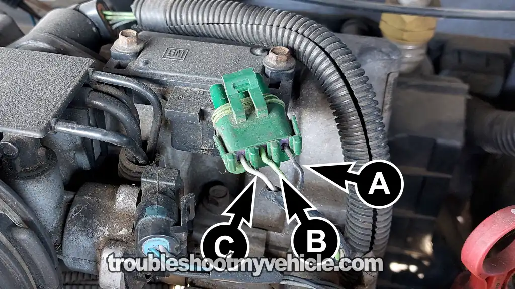
| Wire | Color | Description |
|---|---|---|
| A | Black (BLK) | Ground |
| B | Light green (LT GRN) | MAP signal |
| C | Grey (GRY) | 5 Volts |
TEST 1: Testing The MAP Sensor Signal
In most cases, a failed MAP sensor will produce a voltage signal that doesn't respond to changes in engine vacuum. In other words, the signal stays fixed at one voltage instead of increasing and decreasing as vacuum changes.
To check if the sensor is working correctly, you'll manually apply and release vacuum while monitoring its voltage output with a multimeter.
If the MAP sensor is functioning properly, its output voltage will decrease as vacuum is applied and increase again as the vacuum is released.
NOTE: Don't have a hand-held vacuum pump? No problem. You can apply vacuum to the MAP sensor using your mouth.
IMPORTANT: Leave the MAP sensor plugged into its electrical connector throughout the test. This lets you measure the voltage on the signal wire while the sensor is operating. You'll need to back-probe the connector or use a wire-piercing probe on the signal wire. You can see an example of this tool here: Goupchn 4mm Banana to Banana Plug Test Leads Kit (Amazon affiliate link).
OK, these are the test steps:
- 1
Remove the MAP sensor from its place on the intake manifold.
- 2
If you had to disconnect the MAP sensor from its electrical connector to remove it, reconnect it to the connector now.
- 3
Connect your vacuum pump to the MAP sensor's vacuum inlet.
You'll need to use a piece of vacuum hose to connect the vacuum pump to the MAP sensor. - 4
Place your multimeter in Volts DC mode.
- 5
Connect the black multimeter test lead directly to the battery negative (-) terminal.
- 6
Connect the red multimeter probe to the wire labeled with the letter B (in the image above).
The wire labeled with the letter B is the light green (LT GRN) wire of the connector.
IMPORTANT: The MAP sensor must remain connected to its 3-wire connector. - 7
Turn the key ON but don't start the engine.
- 8
At this point your multimeter should register a value around 4.5 Volts DC.
- 9
Now, pump the vacuum pump to apply vacuum to the MAP sensor. The voltage should decrease.
- 10
Release the vacuum you applied to the MAP sensor. The voltage should increase.
OK, let's examine your test results:
CASE 1: The MAP sensor voltage changed as you applied and released vacuum. This is the expected result and confirms that the MAP sensor is responding correctly to changes in vacuum.
If the check engine light is still on with a MAP sensor trouble code, you can rule out the MAP sensor as the cause of the problem. For more information, see: MAP Sensor Code Won't Go Away.
CASE 2: The MAP sensor voltage did not change as you applied and released vacuum. This usually means the MAP sensor has failed and isn't responding to changes in vacuum.
Before replacing the sensor, verify that it's receiving both the 5-Volt reference signal and Ground. Continue to: TEST 2: Making Sure The MAP Sensor Is Getting 5 Volts.
CASE 3: The multimeter displayed 0 Volts. This result generally indicates that the MAP sensor has failed.
Before condemning the sensor, make sure it's receiving the 5-Volt reference signal and Ground. Continue to: TEST 2: Making Sure The MAP Sensor Is Getting 5 Volts.
TEST 2: Making Sure The MAP Sensor Is Getting 5 Volts
If the MAP sensor's voltage signal didn't change as you applied and released vacuum, the next step is to verify that the sensor is receiving the power it needs to operate.
In this test, you'll check for the 5-Volt reference signal supplied by the fuel injection computer.
This 5-Volt reference is carried to the MAP sensor through the gray (GRY) wire of its 3-wire electrical connector.
In the photo above, this GRY wire is identified by the letter C.
Let's begin:
- 1
Disconnect the MAP sensor from its electrical connector.
- 2
Place your multimeter still in Volts DC mode.
- 3
Now Ground the black multimeter test lead on the battery's negative (-) post.
- 4
Gently probe the female terminal that connects to the wire labeled with the letter C with the red multimeter test lead.
The wire labeled with the letter C, in the photo above, is the GRY of the connector.
NOTE: When probing the front of the female terminal, be careful not to damage it with your multimeter's probe. - 5
Turn the key ON but don't start the engine.
- 6
Your multimeter should show you a voltage value around 4.5 to 5 Volts DC.
OK, let's take a look at what your results mean:
CASE 1: Your multimeter measured 5 Volts. This is the correct test result and confirms that the MAP sensor is receiving its 5-Volt reference signal.
The next step is to verify that the MAP sensor is also getting a good Ground. Go to: TEST 3: Making Sure The MAP Sensor Is Getting Ground.
CASE 2: Your multimeter did not measure 5 Volts. This tells you the MAP sensor isn't receiving the 5-Volt reference signal it needs to operate.
Diagnosing the cause of the missing 5-Volt reference is beyond the scope of this tutorial. Once the problem is repaired and the 5-Volt reference signal is restored, the MAP sensor will be able to operate normally.
TEST 3: Making Sure The MAP Sensor Is Getting Ground
At this point, your test results have confirmed the following:
- TEST 1: The MAP sensor voltage did not change as vacuum was applied and released.
- TEST 2: The MAP sensor is receiving its 5-Volt reference signal.
Your next step is to verify that the MAP sensor is also receiving a good Ground through the black (BLK) wire of its 3-wire connector.
This Ground is supplied by the PCM and is only present with the ignition key in the ON or START position. For this test, leave the engine off and turn the key to the ON position.
In the photo above, the BLK wire is identified by the letter A.
Let's get started:
- 1
Disconnect the MAP sensor from its electrical connector.
- 2
Place your multimeter still in Volts DC mode.
- 3
Connect the red multimeter test lead on the battery's positive (+) post.
- 4
Gently probe the female terminal that connects to the wire labeled with the letter A with the black multimeter test lead.
The wire labeled with the letter A is the BLK wire of the connector.
NOTE: Be careful not to damage the female terminal with your multimeter's probe. - 5
Turn the key ON but don't start the engine.
- 6
Your multimeter register 10 to 12 Volts DC.
Here's what your test result means:
CASE 1: Your multimeter measured 10 to 12 Volts. This is the expected result and confirms that the MAP sensor has a good Ground.
If you've also confirmed the following:
- TEST 1: The MAP sensor voltage did not change as vacuum was applied and released.
- TEST 2: The MAP sensor is receiving its 5-Volt reference signal.
- TEST 3: The MAP sensor has a good Ground.
...then you can conclude that the MAP sensor is defective and needs to be replaced.
CASE 2: Your multimeter did not measure 10 to 12 Volts. This tells you the MAP sensor isn't receiving the Ground it needs to operate.
Tracking down the cause of the missing Ground is beyond the scope of this tutorial. Once the Ground circuit is repaired, the MAP sensor will be able to operate normally.
MAP Sensor Code Won't Go Away
Sometimes, a MAP sensor trouble code keeps coming back even though your tests confirm the MAP sensor is working correctly.
If that's the case, one of the following conditions may be causing the problem:
- Damaged MAP sensor O-ring: The rubber O-ring that seals the MAP sensor to the intake manifold is missing, damaged, or leaking vacuum.
- Low engine vacuum: One or more cylinders may have low engine compression, causing a rough idle and low or unstable manifold vacuum. An engine compression test will help you verify this.
- Intermittent MAP sensor failure: The sensor may work normally most of the time but fail occasionally.
- A simple way to check for this is to lightly tap the MAP sensor with the handle of a screwdriver while applying and releasing vacuum. If the voltage signal suddenly becomes erratic or drops out, the sensor is most likely defective.
- Loose or damaged connector: The MAP sensor electrical connector may not be making a good connection. In many cases, the locking tab breaks and allows the connector to work itself loose, causing an intermittent connection.
- Low fuel pressure: A weak fuel pump may not be supplying enough fuel pressure to the injectors, which can create symptoms that resemble a MAP sensor problem. I recommend testing fuel pressure before replacing any parts.
More 2.2L Buick Century Diagnostic Tutorials
If this tutorial was helpful, be sure and take a look at all of the 2.2L Buick Century diagnostic tutorials in this index:
Here's a sample of the tutorials you'll find there:
- How To Test The TPS With A Multimeter (1993-1996 2.2L Buick Century).
- How To Test For A Blown Head Gasket (1993-1996 2.2L Buick Century).
- How To Test Engine Compression (1993-1996 2.2L Buick Century).
- Common Causes Of Spark Plug Failure (1993-1996 2.2L Buick Century).

If this info saved the day, buy me a beer!
