TEST 3: Making Sure The Radiator Fan Relay Is Getting 12 Volts (Control Circuit)
In this test section, we'll make sure that the radiator fan relay's control circuit is getting power.
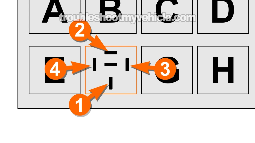
The Power Distribution Center's cavity (slot) that supplies this voltage to the radiator fan relay is the one labeled with number 3 in the illustration 1 of 2 (in the image viewer above).
NOTE: These 10 to 12 Volts will only be present when the key is in the RUN position.
In case you're wondering what the 'control circuit' is: This circuit is basically a coil of wire (inside the relay) that creates a magnetic field when 12 Volts flows through it. This magnetic field pulls a switch closed in the load circuit of the relay to activate the relay.
Let's get started:
- 1
Remove the radiator fan relay from the Power Distribution Center.
- 2
Connect the black multimeter test lead to the negative (-) battery post.
- 3
Turn the key to the RUN position but don't crank or start the engine.
- 4
Probe the female terminal labeled with the number 3 with the red multimeter test lead (using the appropriate too).
IMPORTANT: Avoid inserting the tip of the multimeter test lead directly into the female terminal as this can damage it. Instead, use an adapter whose tip will easily fit into (or probe) the female terminal inside the cavity (slot) of the fuse/relay box. - 5
Your multimeter should give you a reading of 10 to 12 Volts DC.
NOTE: This voltage comes from FUSE 10 of the interior fuse block.
Let's interpret your test result:
CASE 1: 10 to 12 Volts are present. This is the correct and expected test result.
Your next step is to go to: TEST 4: Applying 12 Volts To The Radiator Fan Motor.
CASE 2: 10 to 12 Volts ARE NOT present. This usually means that the radiator fan motor fuse (FUSE 11) is blown.
Check and replace the fuse (if necessary) and repeat the test. Once power is restored, go to: TEST 4: Applying 12 Volts To The Radiator Fan Motor.
TEST 4: Applying 12 Volts To The Radiator Fan Motor
In this test step, we'll apply 12 Volts to the radiator fan motor to verify its operation.
This can easily be accomplished by jumpering the cavities (slots) labeled with the number 1 and number 2 on the radiator fan relay socket on the Power Distribution Center.
IMPORTANT: Before you install the jumper wire, you must be absolutely sure you're jumpering the correct cavities of the radiator fan relay socket on the Power Distribution Center. Jumpering the wrong cavities can cause a short-circuit problem.
Let's get started:
- 1
Remove the radiator fan relay from its socket on the Power Distribution Center (if you haven't already).
- 2
Reconnect the fan motor to its 2-wire connector (if you haven't already).
- 3
Insert one end of your jumper wire into cavity labeled with the number 1.
- 4
Insert the other end of your jumper wire into cavity labeled with the number 2.
- 5
The radiator fan motor should run.
Let's interpret your test result:
CASE 1: The radiator fan motor ran. This is the correct and expected test result.
You can draw one of two conclusions with this test result:
- If the radiator fan motor's amperage draw (as determined in TEST 1) is under 30 Amps, you can conclude that it's OK and functioning correctly. Something else is causing the engine to overheat.
- If the radiator fan motor's amperage draw (as determined in TEST 1) is at or over 30 Amps, you can conclude that it's bad and needs to be replaced (even if it ran in when jumpering the indicated relay socket cavities).
CASE 2: The radiator fan motor DID NOT run. This test result lets you know that the radiator fan motor is bad and needs to be replaced.

If this info saved the day, buy me a beer!


