The intake air temperature (IAT) sensor, on the 1993-1997 1.8L (7A-FE) Toyota Corolla can easily be tested with a multimeter.
In this tutorial, I'll explain how so that you can find out if the IAT sensor is good or bad.
Contents of this tutorial:
- Symptoms Of A Bad Intake Air Temperature (IAT) Sensor.
- What Does The Intake Air Temperature (IAT) Sensor Do?
- Common Intake Air Temperature (IAT) Sensor Problems.
- What Tools Do I Need To Test The IAT Sensor?
- Initial Checks Before Starting The IAT Sensor Tests.
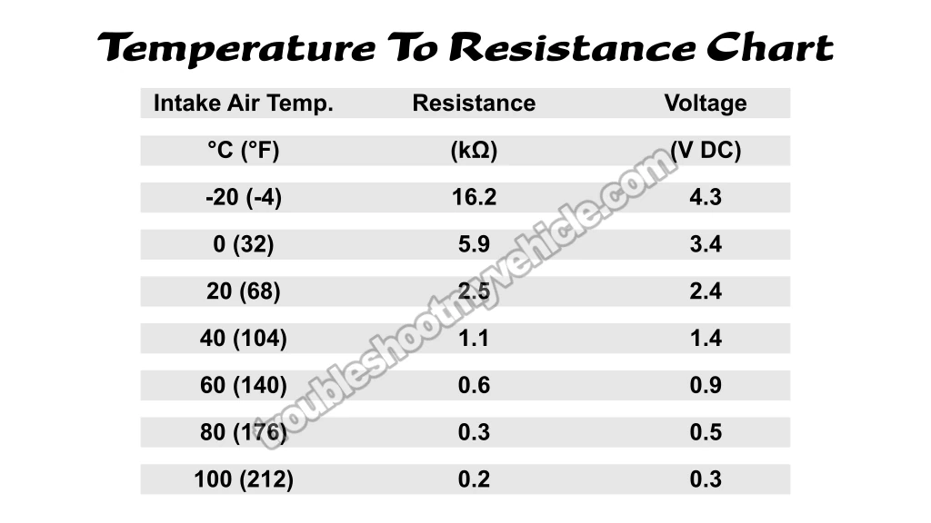
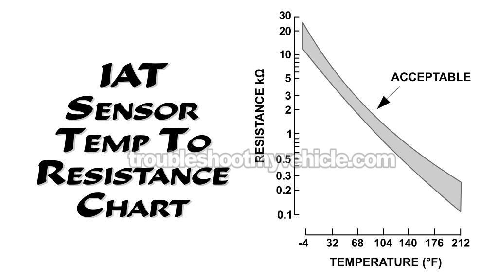
- Checking Temperature To Resistance Value Relationship.
- More 1.8L Toyota Corolla Tutorials.
APPLIES TO: This tutorial applies to the following vehicles:
- 1.8L (7A-FE) Toyota Corolla: 1993, 1994, 1995, 1996, 1997.
- 1.8L (7A-FE) Geo Prizm: 1993, 1994, 1995, 1996, 1997.
Symptoms Of A Bad Intake Air Temperature (IAT) Sensor
The fuel injection system on the 1993-1997 1.8L Toyota Corolla is a speed-density system, and the IAT sensor helps the fuel injection computer estimate incoming air density.
Specifically, the computer uses the data from the IAT sensor, MAP sensor, and engine RPM sensor, to calculate how much air is entering the engine. With this data, it knows exactly how to adjust fuel injection to start and keep the engine running.
A failure or malfunction of the IAT sensor can lead to the following symptoms:
- Check Engine Light (CEL) illuminated, with one of the following trouble codes:
- 1993-1995 OBD I Code 24: Intake Air Temperature (IAT) Sensor Signal.
- 1996-1997 OBD II Code P0110: Intake Air Temperature (IAT) Circuit Malfunction.
- Fuel injection computer activates "limp-in" mode: When the ECM detects a failure in the IAT sensor circuit, it enters a fail-safe or "limp-in" mode, using default values to keep the engine running. This limits engine performance to prevent potential engine damage. You'll see one or more of the following issues:
- Reduced power.
- Poor throttle response.
- Rough idle.
- Engine stalling.
- Engine does not start.
- Higher fuel consumption.
What Does The Intake Air Temperature (IAT) Sensor Do?
The intake air temperature (IAT) sensor measures the temperature of incoming air and sends that data to the fuel injection computer.
Since the IAT sensor is a thermistor, its electrical resistance changes with temperature. The fuel injection computer supplies it with 5 Volts, causing a voltage drop based on its internal resistance.
The computer reads this voltage drop and determines the intake air temperature using pre-programmed values.
Accurate IAT sensor readings are essential for proper fuel injection, ignition timing, and overall engine performance.
Common Intake Air Temperature (IAT) Sensor Problems
There are several common problems that can cause an IAT sensor to fail.
- The IAT sensor simply wears out and its performance degrades over time.
- The IAT sensor suffers an internal open-circuit problem.
- The IAT sensor suffers an internal short-circuit problem.
- The insulation on the wires of the IAT sensor connector has peeled off and the wires are shorted together.
- The locking tab on the IAT sensor connector is broken, resulting in an intermittent connection between the sensor and the ECM.
Any of these conditions will cause the sensor to send an incorrect signal to the engine control module (ECM), resulting in engine performance problems, as well as setting diagnostic trouble codes (DTCs).
What Tools Do I Need To Test The IAT Sensor?
Tools needed to test the IAT sensor:
- A multimeter.
- Optional: An OBD II scan tool with "live data" capability (1996-1997 vehicles).
A "live data" OBD-I scan tool (for the 1993-1995 Corollas) is very expensive —costing thousands of dollars. Luckily, you don't need one to test the IAT sensor.
For the 1996-1997 OBD-II models, a "live data" scan tool can be helpful for checking the IAT sensor in "real time" and reading trouble codes. If you don't have one, don't worry —you don't need one to test the IAT sensor. In this tutorial, I'll show you how to do it with just a multimeter.
What is a must-have tool for the IAT sensor test is a multimeter. I have a few recommendations if you're looking for a fully-featured yet budget-friendly option: Buying A Digital Multimeter For Automotive Diagnostic Testing (at: easyautodiagnostics.com).
Initial Checks Before Starting The IAT Sensor Tests
Before testing the IAT sensor, perform these quick inspections:
- Check the sensor's wiring for any damage, such as cuts or fraying.
- Inspect the connector for cracks or a broken locking tab.
- Examine the sensor itself for cracks (it's made of plastic).
A frayed wire occurs when the insulation is damaged, exposing the metallic strands inside. This is a common issue with the IAT sensor connector.
Frayed wires eventually lead to short-circuits, causing incorrect temperature readings and triggering the check engine light.
Here's an example of this type of problem:
- IAT Sensor Wire Insulation Problem And Wires Shorted Together (at: easyautodiagnostics.com).
Here are two ways to resolve this issue:
- If the fraying is severe or near the connector, replace the entire connector.
- If the damage is minor and further from the connector, wrapping it with electrical tape can provide a temporary fix.
NOTE: Electrical tape is only a short-term solution. For a permanent fix, replacing the damaged connector is the best option.
Checking Temperature To Resistance Value Relationship
As mentioned earlier, as the air temperature changes, the resistance of the IAT sensor also changes. Each resistance value of the sensor corresponds to a specific temperature value.
A good IAT sensor will report a temperature within plus or minus 10 degrees of the ambient temperature of your location.
If the IAT sensor is bad, your multimeter will usually report:
- Open-circuit problem: The multimeter will display "OL" (infinite resistance).
- Short-circuit problem: The multimeter will display "0 Ohms".
IMPORTANT: The accuracy of this resistance-to-temperature test depends on the sensor being completely cold. If the sensor is hot or warm (because the engine has been running), allow it to cool down completely before proceeding with the test.
OK, let's begin:
- 1
Take note of the ambient temperature around you.
Check the temperature on your mobile phone's weather app. If you have a wall-mounted thermometer, use that temp. - 2
Locate the IAT sensor and disconnect it from its connector.
- 3
Remove the IAT sensor from its location on the air filter box.
- 4
Set the multimeter to Ohms mode.
- 5
Measure the resistance value of the IAT sensor across its male terminals.
- 6
Take note of the resistance value the multimeter displays.
- 7
Compare the measured resistance value to the Temperature To Resistance Chart (see images 1 of 3 and 2 of 3 above).
The measured resistance value should fall within the specified range for the current temperature (± 10° F) around you.
Let's interpret your test results:
CASE 1: The resistance value IS NOT within the specified range for the current ambient temperature. This test result tells you the IAT sensor is bad and needs replacement.
CASE 2: The resistance value is within the specified range for the current ambient temperature. This tells you that the IAT sensor is functioning properly.
More 1.8L Toyota Corolla Tutorials
You can find a complete list of tutorials for the Toyota 1.8L Corolla in this index:
Here's a sample of the articles, you'll find in the Index of Articles:
- How To Test The MAP Sensor (1993-1997 1.8L Toyota Corolla).
- How To Test The Throttle Position Sensor (1993-1997 1.8L Toyota Corolla).
- How To Test The Fuel Pump (1993-1997 1.8L Toyota Corolla).
- How To Test Engine Compression (1993-2008 1.8L Toyota Corolla).

If this info saved the day, buy me a beer!


