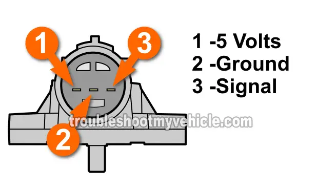
TEST 2: Verifying The MAP Sensor Has Power

The MAP sensor, like any other electrical/electronic device on your Honda, needs power and Ground to work.
So, in this test step, we're gonna' make sure the MAP sensor is getting power.
We'll be using a multimeter to test for this power since it comes in the form of 5 Volts DC (and provided by PCM directly).
NOTE: This test can be done with the MAP sensor connected or disconnected to its electrical connector.
Alright, this is what you'll need to do:
- 1
Place your multimeter in Volts DC mode.
If you don't have a multimeter or need to upgrade yours, check out my recommendation here: Abe's Multimeter Recommendation (at: easyautodiagnostics.com). - 2
Probe the wire that connects to the pin labeled with the number 1 in the image above with the red multimeter test lead.
NOTE: Do not probe the front of the connector with the multimeter's test lead or you'll damage the connector's metal terminal. You should back-probe the connector or use a wire-piercing probe on the wire. - 3
Ground the multimeter's black test lead on a clean and unpainted metal surface on the engine or better yet, on the battery's negative post.
- 4
Turn the key to the ON position (but engine OFF).
Your multimeter should show you 5 Volts DC.
OK, now that the testing part is done, let's take a look at what your results mean:
CASE 1: The multimeter registered 5 Volts. This is the correct result.
The next step is to check that the MAP sensor is getting Ground. For the Ground test, go to: TEST 3: Verifying The MAP Sensor Has Ground.
CASE 2: The multimeter DID NOT register 5 Volts. This results lets you know that the MAP sensor is not bad, since without these 5 Volts DC, the MAP sensor can not function.
Although it's beyond the scope of this article to troubleshoot the cause of these missing 5 Volts, you have now eliminated the MAP sensor as bad. Resolving the issue that is keeping these 5 Volts from being supplied will solve the MAP sensor issue on your Honda vehicle.
TEST 3: Verifying The MAP Sensor Has Ground

So far, you've confirmed that the MAP sensor is getting power (5 Volts DC).
In this test step, you'll verify that the MAP sensor is getting Ground with your multimeter once again.
IMPORTANT: This Ground is provided directly by the PCM, so be very careful and don't short this wire to battery power (12 Volts), or you WILL FRY the PCM.
NOTE: You can perform this test with the MAP sensor connected to its connector or not.
Alright, this is what you'll need to do:
- 1
With your multimeter still in Volts DC mode from the previous test and the key in the ON position (but engine OFF).
- 2
Probe the middle wire of the MAP sensor connector with the black multimeter test lead.
This is the wire that connects to the pin labeled with the number 2 of the MAP sensor (see the image above). - 3
Connect the multimeter's red test lead to the battery's positive (+) post.
- 4
Your multimeter should show 10 to 12 Volts DC.
OK, let's take a look at what your results mean:
CASE 1: The multimeter registered 10 to 12 Volts. This is the normal and correct test result and lets you know that the PCM is providing a good path to Ground for the MAP sensor.
The next step, and the last one, is see if the MAP sensor can react to the changes in air pressure while you apply (and release) vacuum to it. For this test go to: TEST 4: Bench Testing The MAP sensor.
CASE 2: The multimeter DID NOT register 10 to 12 Volts. Double check your multimeter connections and repeat the test.
If your multimeter results still do not indicate 10 to 12 Volts, then the MAP is not fried and not the cause of the MAP sensor diagnostic trouble code (DTC) issue.
Here's why: Without a good path to Ground, that the PCM provides internally, the MAP sensor will not work. With this test result, you have eliminated the MAP sensor as bad.
