This tutorial will help you test the downstream oxygen sensor's on your 4.8L, 5.3L, or 6.0L Chevy or GMC Pickup or SUV. If this tutorial doesn't cover your specific vehicle, take a look at the index of tutorials here: O2 Sensor Tutorial Index.
When one of the downstream O2 sensors goes bad, you'll see either a P0141 and/or P0161 diagnostic trouble code lighting up the check engine light on your instrument cluster. Here are the specifics of each trouble code:
- P0141: HO2S Heater Performance Bank 1 Sensor 2.
- P0161: HO2S Heater Performance Bank 2 Sensor 2.
Contents of this tutorial:
NOTE: The downstream oxygen (O2) sensors are also known as: post catalytic converter oxygen sensors or Rear oxygen sensors.
Before you start testing/troubleshooting Codes P0141 and/or P0161, I highly recommend that you take a look at the following oxygen sensor test primer:
This article answers a lot of the most common questions like:
- Symptoms of A bad oxygen sensor heater element.
- Where are the O2 sensors located?
- What tools do I need?
- What does the heater inside the oxygen sensor do?
Circuit Descriptions Of The Upstream Oxygen Sensors
Each downstream oxygen sensor has four wires. Each one has a specific job to do, and in this section, we'll take a brief look at those job descriptions.
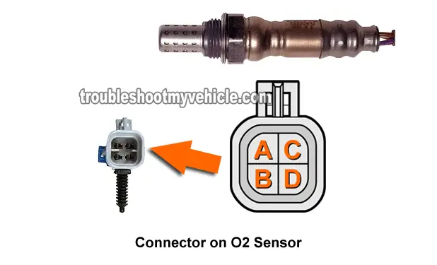
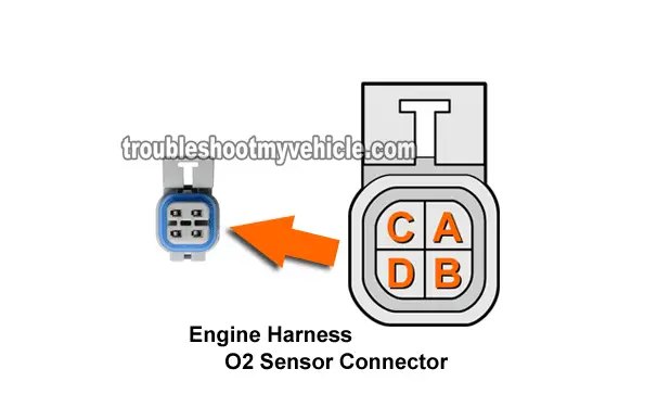
To get into some more specifics: Each wire is identified by a letter. The four letters used are: A, B, C, and D. The two we need to worry about (to troubleshoot Codes P0141 and P0161), are the circuits C and D.
The really good thing about this letter identification, is that you'll find these letters embossed on the oxygen sensor connector too.
NOTE: In the chance that the color of the wires below don't match what's on the downstream oxygen sensor on your specific vehicle, the info in this tutorial still applies. Why? Because you can use the letters (A, B, C, and D) embossed on the connectors to identify the circuits.
| O2 Bank 1 Sensor 2 Circuits (4.8L, 5.3L, 6.0L) | ||
|---|---|---|
| Pin | Wire Color | Description |
| A | Tan w/ White stripe | HO2S Low Signal |
| A <-> | Tan | HO2S Low Signal (Canada built) |
| B | Purple w/ White stripe | HO2S High Signal |
| C | Black | Heater Element Ground (Chassis Ground) |
| D | Pink | Heater Element 12 Volts (O2 sensor fuse) |
| O2 Bank 2 Sensor 1 Circuits (4.8L, 5.3L, 6.0L) | ||
|---|---|---|
| Pin | Wire Color | Description |
| A | Tan | HO2S Low Signal |
| B | Purple | HO2S High Signal |
| C | Black | Heater Element Ground (Chassis Ground) |
| D | Pink | Heater Element 12 Volts (O2 sensor fuse) |
TEST INFO: The Basics Of Testing The Oxygen Sensor Heater Element
IMPORTANT: Perform the downstream oxygen (O2) sensor tests (in this tutorial) with a completely cold engine. If the engine has been running, the upstream and downstream O2 sensors will be EXTREMELY HOT.
If the engine is hot, let it cool down completely. This will give the O2 sensor enough time to cool down too or you run the risk of severe burns from the exhaust pipe or the O2 sensors themselves!
OK, keeping the above safety precautions in mind and in a nutshell, we'll start out our P0141 and/or P0161 troubleshooting tests by making sure that the oxygen sensor's heater element is getting both voltage and Ground.
With the Key On Engine Off, the O2 sensor should get 10 to 12 Volts from an oxygen sensor fuse. Ground is provided internally by the PCM.
Here are some more specifics:
- Power is provided by the D circuit wire.
- This wire will be the Pink wire of the O2 sensor connector (engine wiring harness side).
- Ground is provided by the C wire (4.8L, 5.3L) or the E wire (6.0L).
- This is the Black wire of the O2 sensor connector (engine wiring harness side).
If it turns out that the downstream O2 sensor's heater element is missing power or Ground, well you found the causes of the P0141 and/or P0161 trouble codes.
Now, if both power (10 to 12 Volts DC) and Ground are present, then the next step, is to measure the resistance (with a multimeter) of the heater element inside the oxygen (O2) sensor to see if it's fried or not.
Alright, I'll stop yakking and we'll get testing DTCs P0141 and/or P0161 in the next few pages are the step-by-step testing instructions you'll need to get to the bottom of the problem.
Where To Buy The Oxygen Sensor And Save
You could buy the downstream oxygen sensor at your local auto parts store but you'll end up paying quite a bit for it (I'm sure you've already called and priced the O2 sensor) or you could buy it online and save a few bucks.
Disclosure: As an Amazon Associate, I earn from qualifying purchases. If my tutorials help you, using these links is an easy way to support the site at no extra cost to you. Thank you!
NOTE: Not sure if the o2 sensor fits your particular vehicle? Don't worry. Once you get to the site, they'll ask you for the specifics of your vehicle. If it doesn't fit, they'll find you the right one.
TEST 1: Checking For 12 Volts (Pink Wire)

IMPORTANT: To avoid serious/severe burns, perform all tests in this tutorial with a cold engine and/or cold downstream oxygen sensors. If the engine has been running for any amount of time, then let the engine cool down for about 45 minutes to let the O2 sensors cool down too.
The very first thing you and I will do is to make sure the downstream O2 sensor you're gonna' test is getting power (10 to 12 Volts DC.)
We'll check for this voltage with the Key On Engine Off with either a multimeter or a 12 Volt Test Light
To make sure that you're getting the right amount of voltage, I recommend using a multimeter. If you don't have one or need to upgrade yours, check out my recommendation here: Buying A Digital Multimeter For Automotive Diagnostic Testing at: easyautodiagnostics.com).
OK, to get our P0141/P0161 DTC troubleshooting under way, this is what you need to do:
- Locate the downstream oxygen sensor you need to test
- Bank 1 Sensor 2 is on the 'driver' side of the engine (P0141).
- Bank 2 Sensor 2 is on the 'passenger' side of the engine (P0161).
- If you need more specifics on the location of these downstream O2 sensors, take a look at this primer: How To Locate The Oxygen Sensors.
- Raise the vehicle and support it on jack stands (if applicable) to access the oxygen (O2) sensors.
- Never trust the jack to hold up the vehicle. Use jack stands!
- Disconnect the oxygen sensor from its electrical connector.
- Locate the Pink wire of the engine wiring harness oxygen sensor connector.
- The letter D will be embossed on the connector.
- With the Key On Engine Off, this wire should have 10 to 12 Volts DC.
Let's take a look at your test results:
CASE 1: Your multimeter recorded 10 to 12 Volts DC. This is good, since it confirms that the downstream oxygen (O2) sensor's heater element is being fed with power.
The next step is to make sure that the downstream oxygen sensor's heater element is being fed with Ground on the C circuit wire. For this test, go to: TEST 2: Checking Ground (Circuit C Wire).
CASE 2: Your multimeter DID NOT record the indicated voltage- This usually means that the O2 sensor fuse is blown.
Check the oxygen sensor fuse and if blown, replace and re-test. Although it's beyond the scope of this tutorial to find out why this fuse is blown, the usual cause is that the O2 sensor's wiring has rubbed up against the hot exhaust pipe and has shorted to Ground.
If you do find that the O2 sensor fuse is blown, check the wiring for burned thru' spots. I suggest you also perform TEST 3, to make sure that the heater element inside the O2 sensor has not shorted to Ground internally.

