TEST 2: Checking Blower Relay Voltages
If you've reached this point, you have confirmed that the blower motor resistor assembly is OK and not the cause of the blower problem (either because it tested good in TEST 1 or you've already replaced it).
There's a good chance that the blower motor resistor is not getting fed the voltage it needs to control the blower motor fan speed.
As you may be already aware, it's the HIGH and LOW blower relays that feed the different blower resistor pins with the battery power necessary to create the 3 blower speeds (low, medium and high).
Thankfully, you and I can check these voltages pretty easily and this is the purpose of this test section.
Alright, these are the test steps:
- 1
Unplug the blower motor resistor from its harness connector and turn the key to the On position (but don't start the engine).
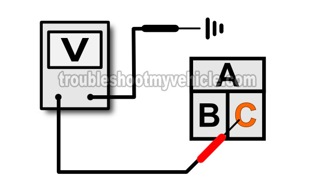
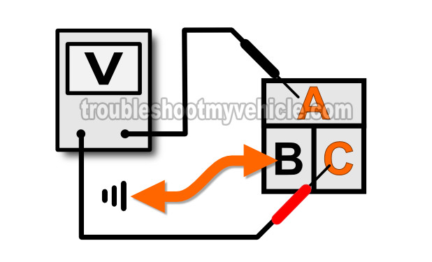
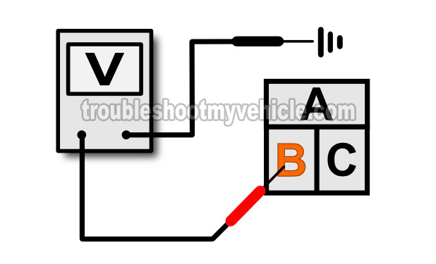
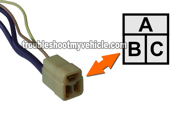
NOTE: All of the tests in this section are done on the blower resistor's harness connector and not on the resistor assembly itself. The illustrations in the image viewer show the front view of the female metal terminals of the blower resistor connector. - 2
Turn the key to the On position and set the blower motor speed to LOW on the A/C Heater control panel.
Terminal C of the blower resistor connector should have 12 Volts DC (see image 1 of 4). - 3
With the ignition key in the On position, set the blower motor speed to MEDIUM on the A/C Heater control panel.
With a jumper wire, Ground terminal B of the blower resistor connector and..
Check voltage across terminals A and C of the blower resistor connector. You should see your multimeter register battery voltage (see image 2 of 4). - 4
With the ignition key in the On position, set the blower motor speed to HIGH on the A/C Heater control panel.
Terminal B should register battery voltage on your multimeter (see image 3 of 4).
Let's take a look at what your test results mean:
CASE 1: In step 2, terminal C DID NOT register battery power. The most likely cause is that the HIGH and LOW blower relay are not getting power or that the A/C Heater control panel is bad.
Although it's beyond the scope of this particular tutorial, your next step is to make sure that the LOW blower relay is getting battery power from its inline fusible link.
CASE 2: In step 3, terminals A and C DID NOT register battery power. The most likely cause is a bad LOW blower relay.
Although it's beyond the scope of this particular tutorial, your next step is to test the LOW blower relay.
CASE 3: In step 4, terminal B DID NOT register battery power. The most likely cause is a bad HIGH blower relay.
Although it's beyond the scope of this particular tutorial, your next step is to test the HIGH blower relay.
CASE 4: All of the test steps above were passed with flying colors. This tells you that the both the LOW and HIGH blower relays are OK and doing their job.
More GM 4.3L, 5.0L, 5.7L Diagnostic Tutorials
If you enjoyed and/or found this 'How To' article helpful, I have written several more 4.3L, 5.0L, 5.7L specific test articles. You can find them all in this index: GM 4.3L, 5.0L, 5.7L Index of Articles.
Here's a small sample of the articles you'll find there:
- MAP Sensor Test (P0106, P0107, P0108) (GM 4.3L, 5.0L, 5.7L).
- How To Test The Engine Compression (GM 4.3L, 5.0L, 5.7L).
- How To Test The Thermostat (GM 4.3L, 5.0L, 5.7L).
- Troubleshooting A Blown Head Gasket (GM 4.3L, 5.0L, 5.7L).
- How To Test The Starter Motor (GM 4.3L, 5.0L, 5.7L).
- How To Test The GM Distributor Mounted Ignition Module (at: easyautodiagnostics.com).

If this info saved the day, buy me a beer!


