Page 2 of 4
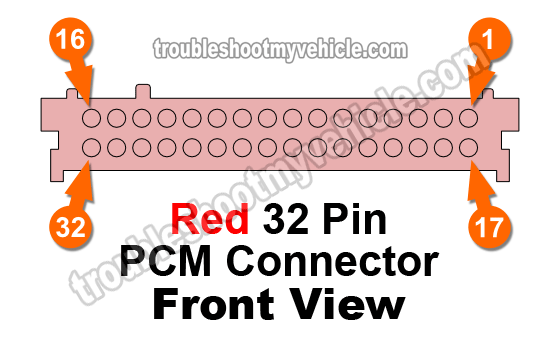
PCM Connector: Red (C2) 1996-1997

To navigate to a different PCM connector, use the links below:
| C2 (Red) PCM 32 Pin Connector | ||
|---|---|---|
| Pin | Wire Color | Description |
| 1 | --- | Empty |
| 2 | --- | Empty |
| 3 | Black | Injector #1 Control |
| 4 | Yellow w/ Black stripe | 2-3 Shift Solenoid (Automatic Transmission only) |
| 5 | --- | Empty |
| 6 | Light Green | 1-2 Shift Solenoid (Automatic Transmission only) |
| 7 | Brown | PWM TCC Solenoid Control (Automatic Transmission only) |
| 8 | --- | Empty |
| 9 | Dark Green w/ White stripe | A/C Relay Enable Relay Control |
| 10 | Brown | EGR Pintle Position |
| 11 | Light Green w/ Black stripe | Injector #2 Control (Except 4.3L) |
| 12 | Red w/ Black stripe | Injector #7 Control |
| 13 | Light Green w/ White stripe | IAC B High |
| 14 | Light Blue w/ White stripe | IAC A High |
| 15 <-> | Light Green w/ Black stripe | Injector #2 Control (4.3L only) |
| 15 <-> | Black w/ White stripe | Injector #5 Control (Except 4.3L) |
| 16 <-> | Pink w/ Black stripe | Injector #3 Control (4.3L only) |
| 16 <-> | Yellow w/ Black stripe | Injector #6 Control (Except 4.3L) |
| 17 | --- | Empty |
| 18 | --- | Empty |
| 19 | Dark Blue | Knock Sensor Signal |
| 20 | --- | Empty |
| 21 | Light Green | MAP Sensor Signal |
| 22 | Tan | Intake Air Temp (IAT) Sensor Signal |
| 23 | Yellow | Engine Coolant Temp (ECT) Signal |
| 24 | Dark Blue | Throttle Position Sensor Signal |
| 25 | --- | Empty |
| 26 | --- | Empty |
| 27 | Yellow w/ Black stripe | TFT Signal (Automatic Transmission Only)) |
| 28 | Yellow | MAF Sensor Signal |
| 29 | Green w/ Black stripe | IAC B Low |
| 30 | Light Blue w/ Black stripe | IAC A Low |
| 31 <-> | Black w/ White stripe | Injector #5 Control |
| 31 <-> | Light Blue w/ Black stripe | Injector #4 Control (Except 4.3L) |
| 32 <-> | Light Blue w/ Black stripe | Injector #5 Control (4.3L Only) |
| 32 <-> | Pink w/ Black stripe | Injector #3 Control (Except 4.3L) |
Safety Precautions
Here are some very important safety precautions when testing the wires coming out of the PCM connectors.
- If one or any of the wires on your GM vehicle DO NOT match the color stated in the Pin Out Charts, then you should not use the Pin Out charts in this article. Why? Because this is the clearest indication that these ARE NOT the Connector Pin Out Charts for your particular vehicle.
- Never probe the front of the connector.
- You should use a wire piercing probe and probe the wire a few inches away from the connector.
- To see what this tool looks like: Wire Piercing Probe.
- You should use a back probe.
- You should use a wire piercing probe and probe the wire a few inches away from the connector.
- This is a FLASH unit and requires reprogramming if replaced with a new one or used one.
- Read the Disclaimer.
