TEST 2: High Speed Wiper Circuit Test

IMPORTANT: If you haven't already disabled the air bag system, do so now. You can find the instructions here: Disabling the Air Bag System (SIR).
So far, you have visually checked the wiper fuse and it's OK. You've also verified that the wiper switch is being fed this power (from the wiper fuse) by testing circuit number 3 of the gray connector (TEST 1).
The next step is to check that the wiper High Speed circuit inside the wiper switch is actually doing its job and routing battery power to the wiper motor when you select the High Speed on the wiper switch.
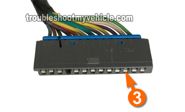
The circuit (wire) that sends this voltage to the wiper motor is the one that's labeled with the number 3 of the gray Multi-Function Switch Connector.
OK, this is what you'll need to do:
- Identify the circuit labeled with the number 3 of the gray connector.
- With an appropriate tool (like a Wire Piercing Probe), probe the wire between the gray connector and the switch.
- The gray connector must remain connected to the instrument panel harness connector at all times during this test.
- Turn the ignition switch to the ON position.
- Set your multimeter to Volts DC mode.
- Ground the black multimeter test lead on a good Ground point.
- Use a battery jump start cable (if you have one) to Ground the black multimeter test lead directly to the battery negative (-) terminal.
- Turn the wiper switch to its High position.
- Your multimeter should register battery voltage (in the range of 10 to 12 Volts DC).
Let's see what your test result means:
CASE 1: Battery voltage (10 to 12 Volts) was present. This is the normal and expected test result and tells you that the High speed circuit inside the wiper switch is OK.
If your GM pickup, van, SUV or mini-van is experiencing a 'No High Speed Wiper' problem, then you have eliminated the wiper switch as the cause. The most likely cause will be a bad wiper motor.
The next test, TEST 3: Low Speed Wiper Switch Circuit, will help you to check the Low speed wiper switch circuit.
CASE 2: Battery voltage (10 to 12 Volts) WAS NOT present. Make sure that that you're testing the correct wire, re-check all of your multimeter connections and repeat the test one more time.
If your multimeter still did not register any voltage (with the key in the ON position), then the wiper switch is bad and needs to be replaced.
There's one more test, that you can do (which is a resistance test of the high speed circuit inside the wiper switch) if you would like to further test the wiper switch and you can find it here: TEST 5: High Speed Circuit Resistance Test.
TEST 3: Low Speed Wiper Switch Circuit

IMPORTANT: If you haven't already disabled the air bag system, do so now. You can find the instructions here: Disabling the Air Bag System (SIR).
In this test step, we're gonna' see if the Low speed circuit inside the wiper switch is good. This test will be done with your multimeter in Ohms (resistance) mode and with the gray connector disconnected from the instrument panel harness connector.
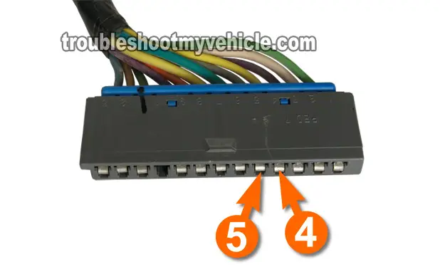
The circuit (wire) that you'll be checking in this test is the one labeled with the number 5 (which is the one that sends the voltage to the wiper motor) and circuit number 4 of the gray turn signal switch connector.
If you have started from the beginning of the article, then you've reached this point because you have confirmed that the wiper switch is getting power (TEST 1) and that the High speed circuit inside the wiper switch is good (TEST 2).
OK, this is what you'll need to do:
- Disconnect the battery negative cable.
- Identify the circuits labeled with the number 4 and number 5 of the gray connector.
- This test is done with the gray connector DISCONNECTED from to the instrument panel harness connector.
- Set the multimeter to Ohms mode:
- With the red multimeter test lead (and an appropriate tool to pierce the wire), probe the wire that corresponds to the number 4.
- With the black multimeter test lead (and an appropriate tool to pierce the wire), probe the wire that corresponds to the number 5.
- The multimeter should read 683 Ohms (.683 K Ohms).
Let's interpret your test result:
CASE 1: Your multimeter registered the indicated resistance. This is the normal and expected test result and tells you that the Low speed wiper switch circuit is OK.
If your GM vehicle is experiencing a 'No Low Speed Wiper' problem, this test result eliminates the wiper switch as bad.
The next test, TEST 4: Wiper Delay (PULSE) Circuits, checks the Wiper Delay (PULSE) circuits.
CASE 2: Your multimeter DID NOT register the indicated resistance. Re-check all of your multimeter connections and repeat the test one more time.
If your multimeter still did not register the indicated resistance value AND:
- The Low Speed Wipers DON'T work.
- The High Speed Wipers DO work.
Then the wiper switch is bad and needs to be replaced.
TEST 4: Wiper Delay (PULSE) Circuits

IMPORTANT: If you haven't already disabled the air bag system, do so now. You can find the instructions here: Disabling the Air Bag System (SIR).
The Wiper Delay mode is also known as the PULSE mode in GM tech speak and in this section we'll test those circuits (inside the wiper switch).
The Delay mode circuits are just a series of resistances (inside the wiper switch) that can be measured with your multimeter in Ohms mode.
The components that handle and control the actual wiper motor delay time, once they get the appropriate signals from the wiper switch, are the Wiper Motor Module and the Solid-State Control Board. Both of these are part of and inside the wiper motor assembly.
The focus of this test section is to test the Wiper Delay circuits inside the wiper switch only since testing the Wiper Motor Module and Solid State Control Board are beyond the scope of this article.
All of the resistance tests, that you'll be doing, will be done on circuits number 5 and circuit number 4 of the gray Multi-Function switch connector.
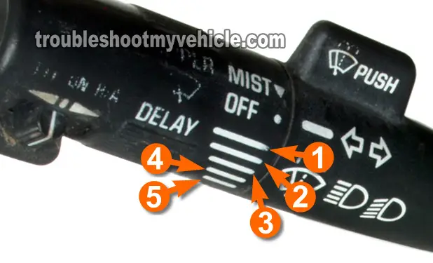
You'll need to use photo above to make sense of the resistance tests you'll do in this section. OK, this is what you'll need to do:
- Disconnect the battery negative (-) terminal.
- Disconnect the gray connector from the instrument panel harness connector.
- Place the Wiper Switch in:
- Delay Speed number 1
- The resistance should be: 430 K Ohms.
- Delay Speed number 2
- The resistance should be: 240 K Ohms.
- Delay Speed number 3
- The resistance should be: 150 K Ohms.
- Delay Speed number 4
- The resistance should be: 67.5 K Ohms.
- Delay Speed number 5
- The resistance should be: 30 K Ohms.
- Delay Speed number 1
Let's see what your test result means:
CASE 1: Your multimeter registered the indicated resistance values for all speeds. This tells you that the Delay (PULSE) circuits inside the wiper switch are OK.
If your GM vehicle still does not have one or several of the Delay speeds working BUT does have Low and High Speed Wipers working, then the Wiper Motor Module and/or Solid-State Control Board inside the wiper motor assembly is bad.
CASE 2: Your multimeter DID NOT register the indicated resistance values. Re-check all of your multimeter connections and repeat the test one more time.
If the multimeter still does not register any of the indicated resistance values, then the wiper switch is bad and needs to be replaced.
