TEST 2: Testing The Continuity Of The Alternator's Battery Circuit

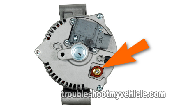
The alternator's output reaches the battery across a single wire. One end of this output wire connects to the back of the alternator (the orange arrow in the photo above points to this location).
The other end of this output wire connects to the positive (+) battery post.
In between the alternator and the positive (+) battery post, a mega fuse or an inline fusible link protects this output wire.
In this test section, you'll check the condition of the output wire's fuse (or inline fusible link) by performing a simple multimeter continuity test.
If the output wire's mega fuse or inline fusible link is OK, your multimeter should report continuity in the circuit.
If the mega fuse or inline fusible link is blown, your multimeter will report an open-circuit condition.
Let's get testing:
- 1
Disconnect the battery negative (-) terminal from the battery. Do not proceed to the next steps till you do this first.
NOTE: Leave the battery positive (+) cable connected to the battery. - 2
Set your multimeter to Ohms mode.
- 3
Connect the red multimeter test lead to the stud behind the alternator. This stud is where the big wire that supplies the alternator's output to the battery attaches to with a nut.
The arrow in the photo above points to the stud location. - 4
Connect the black multimeter test lead to the battery positive (+) terminal.
- 5
Your multimeter should register about 0.5 Ohms to 1 Ohms if the inline fusible link or mega fuse is not blown.
If the output wire's inline fusible link or mega fuse is blown, your multimeter will register an infinite Ohms reading (OL).
Alright, let's interpret your test results:
CASE 1: Your multimeter registered continuity (0.5 to 1 Ohms). This is the correct and expected test result.
With this result you can conclude that the output wire's inline fusible links or mega fuse is OK and not blown.
It's starting to look like the alternator is bad. You still need to perform one last test. For this test, go to: TEST 3: Making Sure The Voltage Regulator Is Receiving 12 Volts.
CASE 2: Your multimeter DID NOT register 0.5 to 1 Ohms, it registered OL. This result tells you that the inline fusible links or mega fuse is blown.
You'll need to replace the inline fusible link or mega fuse and re-test the battery's voltage with the engine running. This should solve your no-charge condition.
TEST 3: Making Sure The Voltage Regulator Is Receiving 12 Volts
If you've reached this point, you have:
- Confirmed that the battery's voltage (with the engine running) is at 12.5 Volts and decreases the longer the engine stays running (TEST 1).
- Confirmed that the mega fuse or inline fusible link is OK (TEST 2).
In this last test section, you'll make sure that the alternator's voltage regulator is receiving 12 Volts.
The wire that delivers these 12 Volts to the alternator's voltage regulator is the yellow with white stripe wire of the voltage regulator's electrical connector.
These are the test steps:
- 1
Reconnect the battery to its battery negative (-) cable.
- 2
Disconnect the voltage regulator from its electrical connector.
- 3
Place your multimeter in Volts DC mode.
- 4
Connect the black multimeter test lead directly to the battery negative (-) terminal.
- 5
Probe the yellow with white stripe (YEL/WHT) wire on the alternator's voltage regulator connector with the red multimeter test lead.
- 6
Your multimeter should register one of two things:
1.) 10 to 12 Volts DC, if the fuse (fusible link) is good.
2.) 0 Volts DC, if the fuse (fusible link) is blown.
Let's take a look at what your specific test results mean:
CASE 1: The multimeter registered 10 to 12 Volts. This is the correct and expected test result. This result lets you know that the fuse (fusible link) is OK.
You can conclude that the alternator is bad and needs replacement if you have:
- Confirmed that the battery voltage is NOT at 13.5 to 14.5 Volts DC with the engine running (TEST 1).
- Confirmed that the alternator's output wire has continuity (TEST 2).
- Confirmed, in this test section, that the YEL/WHT wire has 10 to 12 Volts.
CASE 2: The multimeter DID NOT register 10 to 12 Volts. Please replace the fuse or fusible link with another of the same amperage rating and repeat TEST 1.
More 4.0L Ford Explorer (Aerostar) Tutorials
You can find more 4.0L V6 Ford Explorer (Aerostar) diagnostic tutorials here:
Here's a sample of the tutorials you'll find in the index:
- How To Test For A Blown Head Gasket (1991-2010 4.0L V6 Ford Explorer, Aerostar, And Mercury Mountaineer).
- How To Test The Fuel Pump (1993-2000 4.0L V6 Ford Explorer, Aerostar, And Mercury Mountaineer).
- How To Test Engine Compression (1991-2010 4.0L Ford Explorer, Aerostar, And Mercury Mountaineer).

If this info saved the day, buy me a beer!


