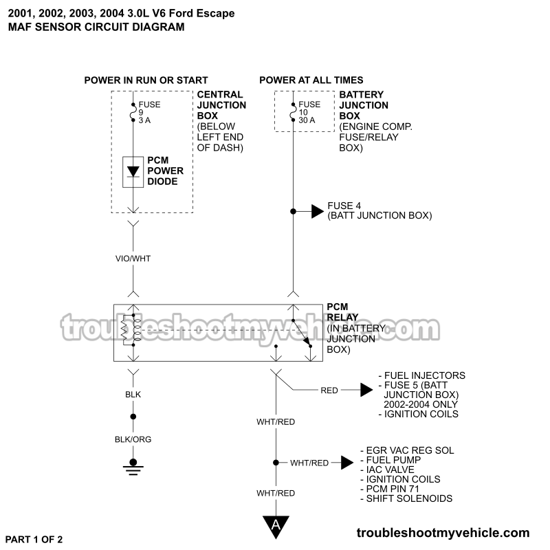

APPLIES TO: This MAF sensor circuit wiring diagram applies to the following vehicles:
- 3.0L V6 Ford Escape: 2001, 2002, 2003, 2004.
The wiring diagram includes the following circuits:
- PCM Power Relay: Located in the Battery Junction Box (BJB), front left corner of engine compartment.
- MAF Sensor: Located on air cleaner assembly box.
MAF SENSOR TEST: This guide walks you through the mass airflow (MAF) sensor test step-by-step:
MAF Sensor Connector Pinout

| Pin | Wire | Description |
|---|---|---|
| 1 | Orange (ORG) | IAT –Intake Air Temp Sensor Signal |
| 2 | White with red stripe (WHT/RED) | VPWR –12 Volts Input in RUN or START |
| 3 | Black (BLK) | PWR GND –Chassis Ground Input |
| 4 | Tan with light blue stripe (TAN/LT BLU) | MAF RTN –MAF sensor Ground (provided by PCM) |
| 5 | Light blue with red stripe (LT BLU/RED) | MAF –MAF signal |
| 6 | Pink with black stripe (PNK/BLK) | SIG RTN –IAT sensor Ground |
More 3.0L V6 Ford Escape Wiring Diagrams And Tutorials
You can find a complete list of wiring diagrams and diagnostic test tutorials here:
Here's a sample of the tutorials you'll find there:
- How To Test The Fuel Injectors (2001-2004 3.0L Ford Escape).
- How To Test The Ignition COP Coils (2001-2007 3.0L V6 Ford Escape).
- How To Test The Cooling Fan Motors (2001-2004 3.0L V6 Ford Escape - Mazda Tribute).
- How To Test For A Blown Head Gasket (2001-2012 3.0L V6 Ford Escape, Mercury Mariner).

If this info saved the day, buy me a beer!

