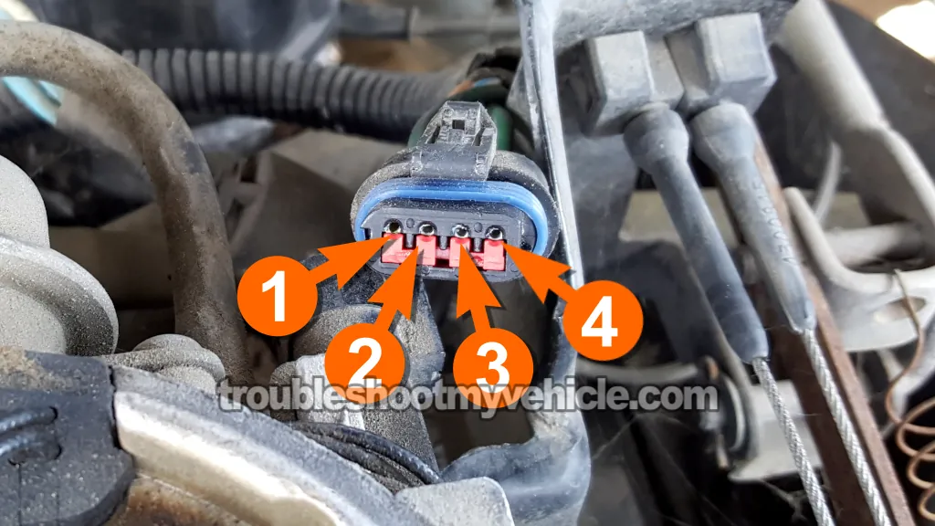
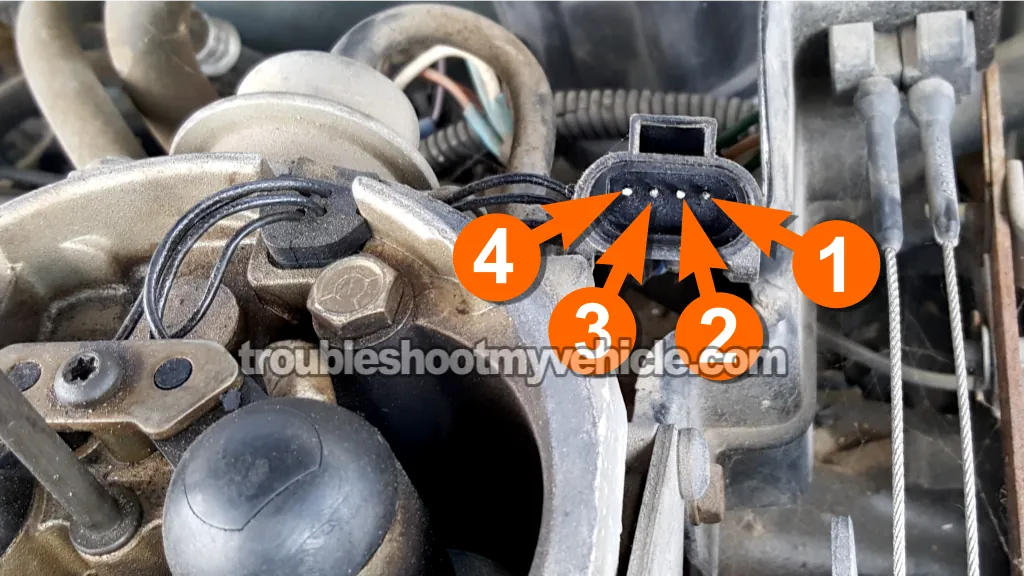
TEST 3: Fuel Injector Resistance Test
NOTE: This test only applies to when you've got one fuel injector spraying fuel and the other isn't.
It's not uncommon for fuel injectors to eventually wear out internally, causing their internal windings to develop a short-circuit or open-circuit failure.
- Open-circuit failure: Your multimeter will show infinite resistance. On a digital multimeter, this usually appears as OL (Over Limit).
- Short-circuit failure: Your multimeter will read very low resistance —typically 0 to 1 Ohm.
We can confirm this by checking the injector's internal resistance. With the engine completely cold, resistance should fall between 10 to 16 Ohms.
Now, since in TEST 1 you've got one injector spraying and one that's not, the non-spraying injector's resistance should closely match the one that is spraying. If it doesn't, the non-spraying injector is faulty.
NOTE: Don't have a multimeter or need to upgrade yours? This is the one I use and recommend: Tekpower TP8268 AC/DC Auto/Manual Range Digital Multimeter (at: amazon.com).
IMPORTANT: We're gonna test the fuel injector resistance at the injectors' 4-wire connector. We're not gonna remove the fuel injector caps to test their resistance. Now, having said that, you can remove the fuel injector caps if you want to test the fuel injector resistance right at the fuel injector terminals.
OK, to get started, this is what you need to do:
- 1
Disconnect the fuel injectors' 4-wire connector.
- 2
Set your multimeter to Ohms mode.
- 3
Measure the resistance between male terminals 1 and 2. See the photo above to identify the connector terminals.
NOTE: You're measuring the resistance between the round male terminals on the connector that belongs to the fuel injectors, not the connector with the round female terminals. - 4
You should see a resistance between 10 to 16 Ohms.
- 5
Measure the resistance between terminals 3 and 4.
- 6
You should see a resistance between 10 to 16 Ohms.
Let's interpret your test results:
CASE 1: The resistance value of both fuel injectors is OK and similar. This result indicates that the non-spraying fuel injector isn't internally damaged.
Although it doesn't have an internal electrical issue, we still need to check a few more things. The next step is to confirm it's receiving power. Go to: TEST 5: Making Sure The Fuel Injector Is Getting Power.
CASE 2: The resistance of one fuel injector (the one with the issue) is not within spec. Retest the fuel injector.
If the resistance is still off and significantly different from the one that is working, your next steps are:
- Remove the plastic hold-down caps from the injectors.
- Test resistance directly on each injector's exposed terminals.
If the non-spraying injector still reads out of spec —or noticeably different from the working one —it's bad and needs to be replaced.
TEST 4: Fuel Injector Activation Signal Test

NOTE: This test section only applies if both injectors aren't spraying fuel in TEST 1.
If you've reached this section, you've confirmed that both fuel injectors are:
- TEST 1: Are not spraying any fuel.
- TEST 2: Are getting power (10 to 12 Volts).
In this test section, we're gonna check the fuel injectors' activation signal using an LED light.
I've found that using an LED is the safest (for the fuel injection computer) and the easiest way to check for the fuel injector activation pulses.
If you don't have an LED light, you can see what one looks like and you can also buy it here: Oznium Flush Mount 12V LED Light (at: amazon.com).
NOTE: Don't use a regular 12 Volt test light for this test. A 12V test light could overload the fuel injector driver circuit inside the fuel injection computer and fry it.
Let's get started:
- 1
Disconnect the 4-wire fuel injector connector. See the photo above to identify this 4-wire connector.
- 2
Connect the red lead of the LED light to terminal 1 of the 4-wire connector.
NOTE: Make sure that the terminal actually connects to one of the dark green with black stripe (DK GRN/BLK) wires of the connector. - 3
Connect the black lead of the LED light to terminal 2 of the connector.
Terminal 2 should connect to the tan (TAN) wire, which delivers the activation signal for injector #2. - 4
Now, have you helper crank the engine.
CAUTION: Be careful and keep your hands and tools away from any moving parts. - 5
The LED should flash ON and OFF the whole time the engine is cranking.
- 6
Remove the red lead of the LED from terminal 2.
- 7
Now, insert the red lead of the LED in terminal 3.
Terminal 3 should connect to the white with dark blue stripe (WHT/DK BLU) wire, which delivers the activation signal for injector #1. - 8
Now, have you helper crank the engine.
CAUTION: Be careful and keep your hands and tools away from any moving parts. - 9
The LED should flash ON and OFF the whole time the engine is cranking.
Let's interpret your test result:
CASE 1: The LED light flashed ON and OFF for both activation signals. This is the correct test result and it confirms that the fuel injection computer is activating the fuel injectors to deliver fuel.
You can conclude that both fuel injectors are bad and need to be replaced if you have confirmed:
- Fuel pump pressure is at 14.5 PSI.
- Both fuel injectors are not injecting fuel (TEST 1).
- Both are receiving 10 to 12 Volts (TEST 2).
- Both are receiving an activation signal from the FI computer (this test).
Fuel pump pressure: If you haven't tested the fuel pump pressure yet, this tutorial will help you with this test:
CASE 2: The LED light DID NOT flash ON and OFF on both terminals. This means the fuel injectors aren't getting activated.
If you have power (confirmed in TEST 2), then the most likely cause of these missing activation signals is an open-circuit issue in the wiring between the injectors and the fuel injection computer.
Your next diagnostic step is to check the continuity of the fuel injector wiring between the injectors and the fuel injection computer connector.
CASE 3: The LED light DID NOT flash ON and OFF on only one terminal. This usually means that the missing activation signal is due to an open-circuit issue in the wiring between the injector and the fuel injection computer (especially if it's getting power -TEST 2).
Your next diagnostic step is to check the continuity of the fuel injector wiring between the injectors and the fuel injection computer connector.
TEST 5: Making Sure The Fuel Injector Is Getting Power
NOTE: This test section only applies if only injector is not spraying fuel.
Since one fuel injector is injecting fuel, we can conclude that the ASD relay and the distributor pickup coil are OK.
We can also conclude that the working injector is getting power. All we have to do is make sure that the non-spraying fuel injector is getting power too.
These are the test steps:
- 1
Disconnect the 4-wire fuel injector connector. See the photo 2 of 2 above to identify this 4-wire connector.
- 2
Connect the black multimeter test lead to the battery negative (-) post.
- 3
Set your multimeter to Volts DC mode.
- 4
Gently probe the terminal 1 of the 4-wire connector with the red multimeter test lead.
Make sure that this connects to one of the dark green with black stripe (DK GRN/BLK) wires of the connector. - 5
Have you helper turn the key to the ON position but not crank the engine.
- 6
Your multimeter should register 10 to 12 Volts DC for around 3 seconds.
This is the key on engine off (KOEO) power test.
Power will get shut off by the fuel injection computer if the engine isn't cranked (this is normal). - 7
Now, have you helper crank the engine.
CAUTION: Be careful and keep your hands and tools away from any moving parts. - 8
Your multimeter should register 10 to 12 Volts DC the entire time the engine is cranking.
This is the key on engine running (KOER) power test. - 9
Repeat the voltage test on terminal 4.
NOTE: Make sure the terminal connects to the other dark green with black stripe (DK GRN/BLK) wire.
Let's interpret your test result:
CASE 1: 10 to 12 Volts are present in both KOEO and KOER parts on both terminals. This is the correct and expected test result.
Now that we know that the non-spraying fuel injector is getting power, we need to see if it's getting an activation signal. Go to: TEST 6: Making Sure The Fuel Injector Is Getting An Activation Signal.
CASE 2: 10 to 12 Volts ARE NOT present in both KOEO and KOER parts in one terminal. This confirms that the non-spraying fuel injector isn't getting the power and that the other is.
The most likely cause is an open-circuit problem in the wiring between the injector and the engine wiring harness. Although it's beyond the scope of this tutorial, your next step is to find out why this voltage is missing and restore it to the circuit.


