In this tutorial I'm gonna' show you how to test the intake air temperature (IAT) sensor of your Toyota equipped with a 1.8L 4 cylinder engine.
The intake air temperature (IAT) sensor is part of the mass airflow (MAF) sensor assembly and it can be easily tested with either a scan tool or a multimeter and I'll show you how.
Contents of this tutorial:
- Symptoms Of A Bad IAT Sensor.
- What Tools Do I Need To Test The IAT Sensor?
- What Does The IAT Sensor Do?
- TEST 1: Checking The Intake Air Temperature Value.
- TEST 2: IAT Sensor Circuit High Voltage.
- TEST 3: IAT Sensor Circuit Low Voltage.
- TEST 4: Unplugging The IAT Sensor.
- TEST 5: Jumpering The IAT Sensor Circuits.
- TEST 6: IAT Sensor Resistance Test (P0112).
- TEST 7: IAT Sensor Resistance Test (P0113).
- TEST 8: 5 Volt Reference Circuit.
- Intake Air Temp (IAT) Temperature/Resistance Chart.
- IAT Sensor Test Summary.
- More 1.8L Toyota Corolla Tutorials.
ES ![]() You can find this tutorial in Spanish here: Cómo Probar El Sensor IAT (1.8L Toyota Corolla) (at: autotecnico-online.com).
You can find this tutorial in Spanish here: Cómo Probar El Sensor IAT (1.8L Toyota Corolla) (at: autotecnico-online.com).
APPLIES TO: This tutorial applies to the following vehicles:
- 1.8L Toyota Celica: 2000, 2001, 2002, 2003, 2004, 2005.
- 1.8L Toyota Corolla: 2003, 2004, 2005, 2006, 2007, 2008.
- 1.8L Toyota Matrix: 2003, 2004, 2005, 2006, 2007, 2008.
- 1.8L Toyota MR2 Spyder: 2000, 2001, 2002, 2003, 2004, 2005.
Symptoms Of A Bad IAT Sensor
When the intake air temperature (IAT) sensor on your Toyota goes bad, the check engine light (CEL) will immediately illuminate to let you know that there's a problem and that a diagnostic trouble code has set to indicate a problem.
Here are some of the specific symptoms you'll see/have:
- Diagnostic trouble codes:
- P0110: Intake Air Temperature Circuit Malfunction.
- P0112: Intake Air Temperature (IAT) Sensor Circuit Low Voltage.
- When your scan tool reports this DTC, the IAT sensor is reporting a temperature of 284 °F (140 °C) or hotter.
- P0113: Intake Air Temperature (IAT) Sensor Circuit High Voltage.
- When your scan tool reports this DTC, the IAT sensor is reporting a temperature of -40 °F (-40 °C) or colder.
- Bad gas mileage.
- Black smoke coming out of the tailpipe.
- Won't pass the emissions test.
What Tools Do I Need To Test The IAT Sensor?
Here's a basic list of tools you'll need:
- A multimeter.
- If you need to upgrade or buy a multimeter, check out my recommendation: Buying A Digital Multimeter For Automotive Diagnostic Testing (found at: easyautodiagnostics.com).
- Scan tool.
- Don't have one? Check out my recommendation: Abe's Scan Tool Recommendation.
- Wire piercing probe.
- Although this tool is not an absolute must, if you do buy one, you'll realize just how easy it makes testing the voltages inside the wires.
- If you need to see what this tool looks like, you can see it here: Wire Piercing Probe.
What Does The IAT Sensor Do?

The intake air temperature sensor's job is to take a measurement of the temperature of the incoming air (that the engine is breathing) and then send this info to the PCM.
Once the PCM gets it, it uses this info to better calculate the mass of the air entering the engine.
To get into a little more detail: your Toyota's PCM needs to know two very important things (among several) to calculate the correct amount of fuel to inject for the amount of air the engine is breathing.
These two things are:
- Temperature of the incoming air.
- The flow rate of the air the engine is breathing.
It all boils down to the fact that temperature has a direct effect on air density (mass) and since the MAF sensor can only measure the flow rate of air passing thru' it, the IAT sensor helps the PCM to further ascertain the precise amount of air entering the engine (and this is one of the reasons why the intake air temperature sensor is part of the mass airflow sensor assembly).
This in turn helps the PCM maximize everything from fuel consumption to performance.
OK, these are the circuit descriptions of the mass air flow (MAF) sensor and the intake air temperature (IAT) sensor:
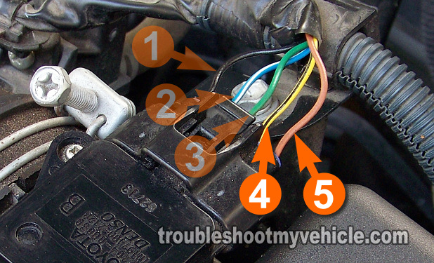
| MAF Sensor Connector Pin Out | ||
|---|---|---|
| Pin | Wire Color | Description |
| 1 | Black | Fused power (12 Volts) |
| 2 | Blue w/ White stripe | MAF sensor Ground (PCM) |
| 3 | Green | MAF sensor signal |
| 4 | Yellow w/ Black stripe | Intake Air Temp (IAT) Sensor |
| 5 | Brown | Intake Air Temp (IAT) Sensor |
As you're probably already aware, the MAF sensor on your Toyota has 5 wires coming out of its connector. We only need to be concerned with 2 of the 5 wires since the other 3 belong to the MAF sensor that is part of the assembly.
TEST 1: Checking The Intake Air Temperature Value

When the intake air temperature sensor goes bad, it usually sends the computer an extreme temperature output. Which the computer interprets as an extremely cold or hot temperature.
To be a bit more specific: Depending on how the sensor has gone bad, it will tell the computer that the incoming air is at an extremely cold temperature or an extremely hot temperature.
So the very first thing that you and I need to do, before anything else, is to hook up a scan tool (to the car) and check what air temperature the sensor is reporting to the PCM (Powertrain Control Module = Fuel Injection Computer).
This of course requires a scan tool that can read Live Data (if you don't have a scan tool and you need to buy one, check out my Actron CP9580 Scan Tool Review).
OK, this is what you need to do:
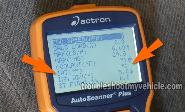
- Connect your scan tool to your Toyota.
- Once the scan tool has powered up, go to its Live Data mode.
- Scroll down to the PID labeled IAT (°F)
- In case you're wondering, PID stands for: Parameter ID (ID = Identification).
- The scan tool should register a temperature that should be within ±10 °F of ambient temperature (if all is normal)
- So let's say that it's 50 °F outside, then the IAT sensor PID should register something between 40 to 60 °F.
- Now, since you're here because you have an IAT sensor diagnostic trouble code (DTC), more than likely you'll see one of the following:
- -40 °F (-40 °C) or colder.
- OR 284 °F (140 °C) or hotter.
Let's interpret your test results:
CASE 1: Your scan tool shows a -40 °F (-40 °C) or colder reading. This extreme cold temperature reading clearly indicates that there's a problem with the intake air temperature sensor or its circuits.
This temperature reading also confirms that the diagnostic trouble code P0113 (IAT Sensor Circuit High Voltage) that you retrieved from the PCM's memory is right on the money.
The most likely cause will be that the circuit is ‘open’ somewhere inside the MAF sensor (remember the IAT sensor is part of the MAF sensor assembly).
We'll find out in the next couple of tests. Go to: TEST 2: IAT Sensor Circuit High Voltage.
CASE 2: Your scan tool shows a 284 °F (140 °C) or higher reading. This extreme hot temperature reading clearly indicates that there's a problem with the intake air temperature sensor or its circuits.
This temperature reading also confirms that the diagnostic trouble code P0112 (IAT Sensor Circuit Low Voltage) that you retrieved from the PCM's memory is right on the money.
To further your diagnostic of the IAT sensor, go to: TEST 3: IAT Sensor Circuit Low Voltage.
CASE 3: Your scan tool shows a temperature reading that's ±10 °F of ambient temperature. This test result tells you that at the moment the IAT sensor is functioning correctly.
But, since you still have a DTC P0112 or P0113 registered on your PCM's memory, I recommend clearing the diagnostic trouble code (DTC) and road testing your vehicle to see if the code comes back.
If it does, repeat this test once more.
