TEST 3: Making Sure The Igniter Is Getting Ground

So far, you made sure that:
- All four cylinders are not getting spark.
- The igniter is getting power.
In this test step, we're gonna' make sure that the igniter (ignition module) is getting Ground.
Ground is fed to the igniter by the black with white stripe (BLK/WHT) wire of the number 3 terminal of the harness connector.
Let's get started:
- 1
Disconnect the igniter from its 8-wire electrical connector.
- 2
Place your multimeter in Volts DC mode.
- 3
Connect the black multimeter test lead to the WHT/BLK wire of the igniter's electrical connector.
This is the wire that connects to terminal number 3 in the illustration above (of the igniter's harness connector). - 4
Connect the red multimeter test lead to the battery positive (+) terminal.
- 5
Your multimeter should read 10 to 12 Volts DC with the Key On and Off (if Ground is present).
Let's take a look at what your test results mean:
CASE 1: The igniter is getting Ground. This is the correct and expected test result.
The next step is to make sure the igniter is getting the IGT signals from the fuel injection computer. For this step, go to: TEST 4: Testing The Igniter Control Signals.
CASE 2: The igniter IS NOT getting Ground. This tells you that the igniter is not working due to a lack of chassis Ground.
Your next step is to find out why this Ground is missing and restore it. Once Ground is restored, the igniter should function again.
TEST 4: Testing The Igniter Control Signals


So far, you made sure that:
- All four cylinders are not getting spark.
- The igniter is getting battery power and Ground.
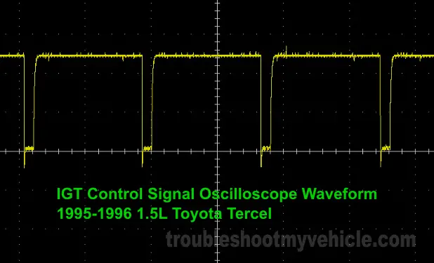
In this test step, we're gonna' use an LED light to see if the igniter (ignition module) is getting the IGT1 and IGT2 control signals from the fuel injection computer.
The IGT1 signal is fed to the igniter by the light green (LT GRN) wire of the number 5 terminal of the harness connector. The IGT1 signal is the one that tells the igniter to activate the ignition coil for cylinders #1 and #4.
The IGT2 signal is fed to the igniter by the blue with yellow stripe (BLU/YEL) wire of the number 4 terminal of the harness connector. The IGT2 signal is the one that tells the igniter to activate the ignition coil for cylinders #2 and #3.
IMPORTANT: You'll need to use an automotive LED light with a built in resistor. A 12 Volt test light will not work and can damage the igniter. You can see an example of this LED (with built in resistor) here: The LED Light Test Tool and How To Make One (at: easyautodiagnostics.com).
IMPORTANT: The igniter must remain connected to its electrical connector for this test to function. To access the IGT signals inside the wire, you'll need to use either a back probe or a wiring piercing probe. You can see an example of a wiring piercing probe here: Wire Piercing Probe Review (Power Probe PWPPPPP01) (at: easyautodiagnostics.com).
These are the test steps:
- 1
Connect the red LED wire to the LT GRN wire of the igniter's electrical connector. This is the wire that connects to terminal number 5 in the illustration above (of the igniter's harness connector).
NOTE: The igniter must remain connected to its electrical connector. - 2
Connect the black LED wire to the battery negative (-) terminal.
- 3
After the LED light is set up, have your helper crank the engine as you observe the LED light.
- 4
The LED light should flash ON and OFF in steady pulses as the engine is cranking if the IGT1 signal is present.
- 5
Repeat steps 1 thru' 4 on the BLU/YEL wire to test for the IGT2.
Let's take a look at what your test results mean:
CASE 1: The LED light flashed on both circuits (wires) tested. This is the correct and expected test result and tells you that the igniter is getting the IGT1 and IGT2 control signals from the fuel injection computer.
The next step is to make sure that the igniter is now creating the activation signal for the 1/4 ignition coil and the 2/3 ignition coil. For this step, go to: TEST 5: Testing The Ignition Coil Control Signals.
CASE 2: The LED light DID NOT flash on both circuits (wires) tested. This tells you that the igniter is not activating the ignition coils due to a lack of the IGT control signals.
The most common reason the IGT1 and IGT2 signals are missing is a defective crankshaft position sensor. Although it's beyond the scope of this tutorial to test the crankshaft position (CKP) sensor, your next step is to test it:

