
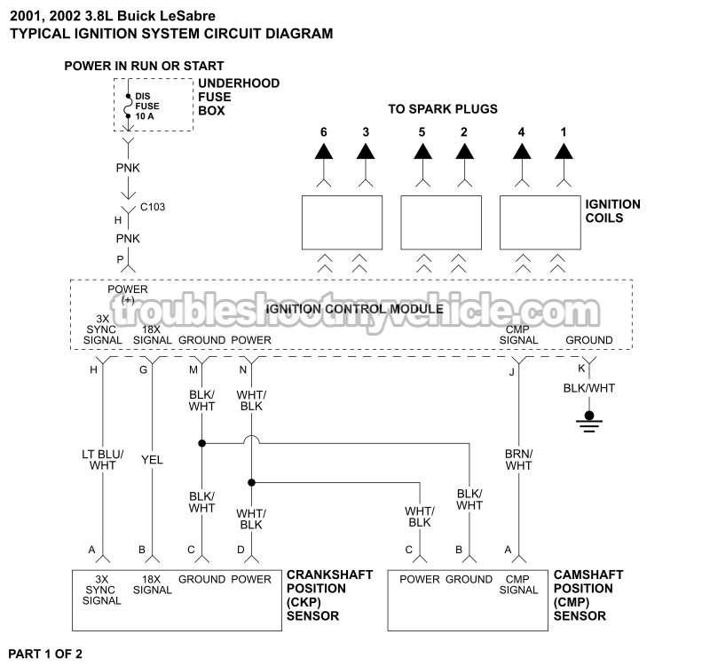
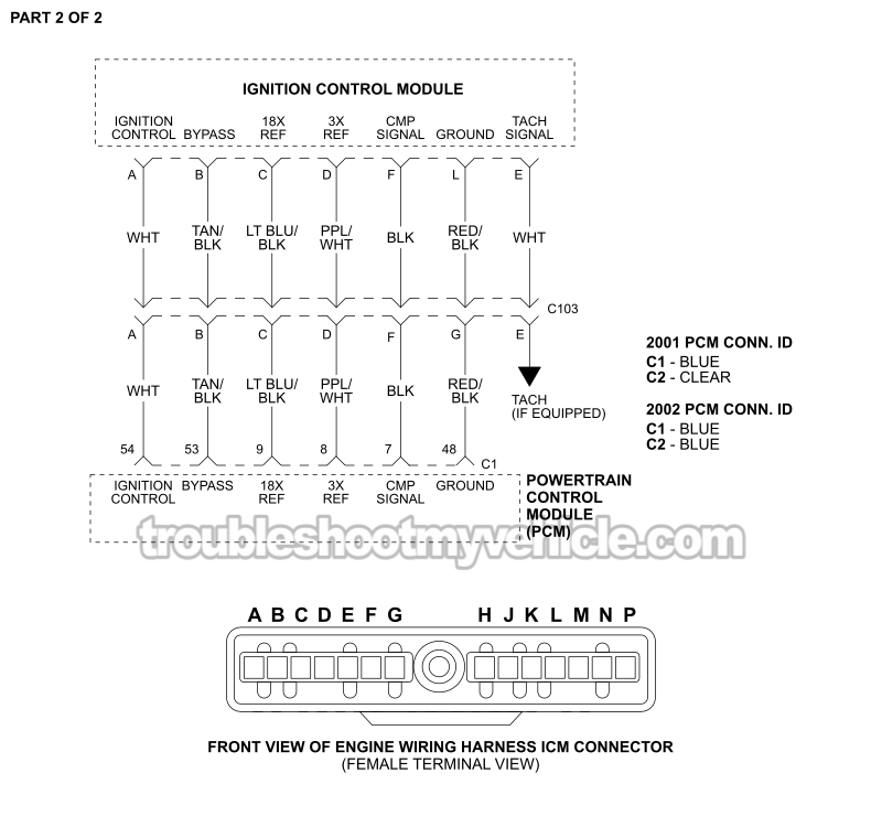
APPLIES TO: This ignition control module (ICM), CKP and CMP sensor circuit wiring diagram applies to the following vehicles:
- 3.8L V6 Buick LeSabre: 2001, 2002.
Ignition System Basic Operating Theory
Here are the basics you need to know to diagnose the ignition control module, crankshaft position sensor, and camshaft position sensor:
Ignition Control Module (ICM)
The ignition control module (ICM) is the component that manages the ignition system during cranking and works closely with the PCM after the engine starts. It powers the crankshaft position sensor, interprets the signals it produces, fires the ignition coils in the correct sequence, and sends engine speed and crankshaft position information to the PCM.
Without accurate crankshaft position signals, the ICM doesn't know when to fire the ignition coils. The result is usually a no-spark, cranks-but-doesn't-start condition.
Crankshaft Position (CKP) Sensor
The crankshaft position sensor contains two Hall-effect sensors inside one housing. As the crankshaft turns, interrupter rings mounted behind the harmonic balancer create two digital ON/OFF signals that the ignition control module constantly monitors.
The ICM uses these signals to determine both crankshaft position and engine speed. We've got to have both signals present for the ignition system to operate correctly, so a problem with either one can prevent the engine from starting.
CKP SENSOR TESTS: How To Test The CKP Sensor With A Multimeter (1994-2005 3.8L V6 Buick LeSabre).
Camshaft Position (CMP) Sensor
The camshaft position sensor lets the PCM know when cylinder #1 is on its power stroke. The PCM uses this information to synchronize sequential fuel injection for the best performance and fuel economy.
If the CMP signal is lost, the engine will usually still start and run using a backup strategy, although it'll often set a diagnostic trouble code like P0341.
One very common failure on these engines has nothing to do with the sensor itself. The small magnet attached to the camshaft sprocket is held in place by a plastic carrier that's known to crack and break with age. When the magnet falls off, the CMP sensor can't generate its signal, making it appear that the sensor has failed when the real problem is the missing magnet.
CMP SENSOR DIAGNOSTIC TESTS: How To Test The CMP Sensor -P0341 (1994-2005 3.8L V6 Buick LeSabre).
Other ICM, CKP And CMP Sensor Wiring Diagrams
- ICM And CKP/CMP Sensor Circuit Wiring Diagram (1994-1995 3.8L V6 Buick LeSabre).
- ICM And CKP/CMP Sensor Circuit Wiring Diagram (1996-1997 3.8L V6 Buick LeSabre).
- ICM And CKP/CMP Sensor Circuit Wiring Diagram (1998-2000 3.8L V6 Buick LeSabre).
- ICM And CKP/CMP Sensor Circuit Wiring Diagram (2003-2005 3.8L V6 Buick LeSabre).
More 3.8L V6 Buick LeSabre Tutorials
You can find a complete list of 3.8L V6 Buick LeSabre tutorials and wiring diagrams in this index:
Here's a sample of the tutorials you'll find in the index:
- How To Test Engine Compression (1994-2005 3.8L V6 Buick LeSabre).
- Common Causes Of Spark Plug Failure (1994-2005 3.8L V6 Buick LeSabre).
- How To Test For A Blown Head Gasket (1994-2005 3.8L V6 Buick LeSabre).
- How To Test The TPS With A Multimeter (1996-2005 3.8L V6 Buick LeSabre).

If this info saved the day, buy me a beer!
