TEST 7: IAT Sensor Resistance Test (P0113)

In this test step, you're gonna check the resistance of the intake air temperature (IAT) sensor with your multimeter in Ohms mode to see if the IAT sensor is bad.
What you're gonna' do, is to see if the IAT sensor is ‘open’ by doing a resistance test and using the ‘IAT Sensor Temperature to Resistance’ chart found here: IAT Sensor Temperature / Resistance Relationship (which, by the way, is in the next page).
OK, to get this test going, this is what you need to do:
- Disconnect the MAF sensor connector and remove the MAF sensor.
- You don't have to remove the MAF sensor, but, it'll be easier to do this test with the MAF sensor removed.
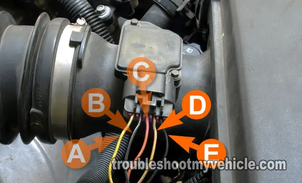
- On the MAF sensor, locate the pins that correspond to the letters D and E of the MAF connector.
- With your multimeter in Ohms (Ω) mode:
- Measure the resistance of the intake air temperature (IAT) sensor.
- What you're looking for, is to see if the IAT sensor records a resistance that indicates a temperature of -30 to -40 °F.
- Specifically: What you're looking for, is a resistance that is at 100,700 Ohms (100.7 K Ohms) or more.
- See the Temperature/Resistance Chart in the next page.
Let's interpret your test results:
CASE 1: The multimeter recorded a resistance of 100.7 K Ohms or more- This tells you that the intake air temperature (IAT) sensor inside the mass air flow (MAF) sensor is bad.
Since the IAT sensor is part of the MAF sensor, you'll need to replace the entire MAF sensor to solve the P0113 (Intake Air Temperature (IAT) Sensor Circuit High Voltage) Diagnostic Trouble Code.
CASE 2: The multimeter DID NOT record a resistance of 100.7 K Ohms- So far so good, but you're not out of the woods yet.
What you now need to do, is to see if the IAT sensor resistance equals to the ambient (surrounding) temperature of where you're testing your vehicle.
For example, if I'm testing my Chevy Colorado outside and it's a balmy 95 °F. Then the temperature that the IAT sensor should record (in ohms of course) should be within ±10 °F of 95 °F. Using the Temperature / Resistance Chart in the next page, the IAT sensor resistance should be somewhere between 177 and 332 Ohms (0.177 and 0.332 K Ohms).
NOTE: If the IAT sensor checks out good (according the Temperature/Resistance Chart in the next page) The next step is to check that the IAT sensor is getting power, in the form of 5 Volts and Ground. For this info, go to: TEST 8: 5 Volt Reference Circuit.
TEST 8: 5 Volt Reference Circuit

In this section, we're gonna' check the intake air temperature (IAT) sensor's 2 circuits in one test.
These two circuits are the 5 Volt Reference circuit (wire letter D) and Ground circuit (wire letter E).
What we'll do is unplug the MAF sensor and then probe these 2 wires (of the MAF sensor connector itself) with your multimeter in Volts DC mode.
NOTE: That's right, the test has to be done with the MAF sensor disconnected and as such, here are some important precautions to keep in mind:
- Don't probe the front of the MAF sensor connector with the multimeter Leads. This can damage them and then you're gonna' be in a heap of trouble later when the connector causes a false contact.
- You can back probe the connector with special back probes.
- Or, do what I do: use wire piercing probes.
OK, safety lesson over, this what you'll need to do to get this test done:
- Place the multimeter in Volts DC mode.
- Disconnect the mass air flow (MAF) sensor from its connector.
- Locate the wires identified with the letter D and letter E.
- Wire D is the Tan wire.
- Wire E is the Black w/ White stripe wire.
- Connect the red multimeter test lead to this letter D wire using an appropriate tool (like a Wire Piercing Probe).
- Connect the black multimeter test lead to the letter E wire.
- Turn the key to the ON position (RUN position)
- Your multimeter should register 4.5 to 5 Volts DC.
- When done, turn the key Off and interpret your results below:
CASE 1: The multimeter recorded 4.5 to 5 Volts DC- So far so good, since this test result tells you that two very important things:
- That the PCM is supplying 5 Volts on wire D.
- That the PCM is supplying a Ground on wire E.
NOTE: If you're coming from TEST 7 or TEST 8, then this result tells you that the most likely cause of the DTC P0113 (Intake Air Temperature (IAT) Sensor Circuit High Voltage) or DTC P0112 (Intake Air Temperature (IAT) Sensor Circuit Low Voltage) is an intermittent short. Intermittent problems are the hardest to find and resolve. I suggest erasing the DTC and road testing the vehicle to see if the DTC P0112 or P0113 comes back and repeating the tests.
CASE 2: The multimeter DID NOT record 4.5 to 5 Volts DC. Make sure that you're testing the correct wires, that your connections are OK, and repeat the test.
Then there's one of two things wrong:
- That the PCM (Fuel Injection Computer) IS NOT supplying 5 Volts on wire D.
- That the PCM (Fuel Injection Computer) IS NOT supplying a Ground on wire E.
NOTE: This test result exonerates the IAT Sensor as bad, since without power (5 Volts) or Ground, the IAT Sensor won't work.
You'll need to troubleshoot the missing 5 Volt Reference Signal or the Ground to resolve the IAT sensor problem and Diagnostic Trouble Code (DTC).
