If the blower motor in your Ford vehicle only works in one speed (usually just high), then there's a good chance that the blower motor resistor is bad and behind the problem.
Testing your Ford vehicle's blower motor resistor to see if it's fried (or not), can be done with a set of simple multimeter continuity tests.
In this tutorial, I'll show you how to get it done in a step-by-step way.
NOTE: Even though this tutorial is filed in the Ford 4.9L, 5.0L, 5.8L index of this website, it applies to quite a few Ford vehicles. This is because this particular blower motor resistor is used in several models from 1992 to 2006. To find out if your particular Ford vehicle is covered by this troubleshooting tutorial, check the box titled “Applies To:” on the right column.
To further help you in knowing if this tutorial applies to your Ford car, mini-van, pickup or SUV, if your vehicle uses one of the following blower motor resistor numbers, then this tutorial applies to your vehicle:
- Airtex/Wells 3A1124.
- Dorman 973011 and 973412.
- Duralast JA1176.
- Four Seasons 20261.
- Motorcraft 20261.
- Standard Motor Products RU318.
Contents of this tutorial:
The following tutorial on testing the blower switch may come in handy:
Basics Of Troubleshooting The Blower Control Resistor

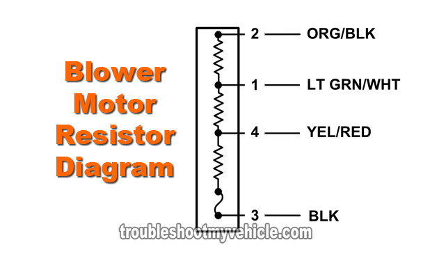
The Ford blower motor resistor assembly, covered by this tutorial, has 3 different resistors in series.
The purpose of these resistors is to reduce the amount of the blower motor's current that's passing through them (as you're probably already aware, these resistors are located between the blower motor and Ground).
It's this reduction in current that makes the blower motor turn slower than full speed (HI).
Now to be a bit more specific, to achieve LO or M1 or M2 blower motor speeds, the blower motor switch is the component responsible for rerouting the blower motor's current through a specific combination of these resistors (within the blower motor resistor assembly). Here's the breakdown:
- To achieve LO speed:
- Current passes thru' all 3 resistors.
- To achieve M1 speed:
- Current passes thru' only 2 resistors.
- To achieve M2 speed:
- Current passes thru' only 1 resistor.
The one blower motor speed that doesn't depend on the blower motor resistor assembly is HI since the blower motor switch accomplishes this speed by completely bypassing the blower motor resistor assembly.
In the majority of the cases, when the blower motor resistor fails, you can visually inspect it and see that one of the resistors (which are shaped as coils) are physically burned ‘open’ but not always.
The cool thing is that you can check the integrity of each resistor and the state of the thermal fuse with a multimeter and that's how I'll show you how to test it in this tutorial.
| Blower Resistor Circuit Descriptions | ||
|---|---|---|
| Pin | Wire Color | Description |
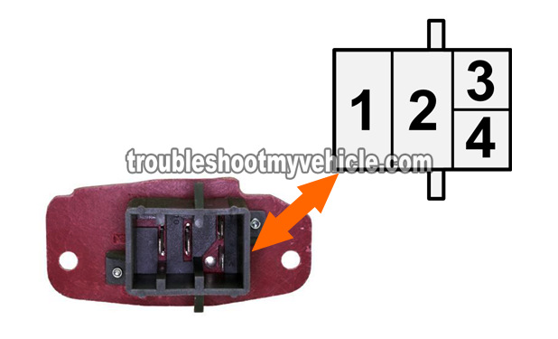
| 1 | LT GRN/WHT | M1 Speed Input From Blower Switch. |
| 2 | ORG/BLK | Input From Blower Motor. |
| 3 | BLK | Output to Chassis Ground. |
| 4 | YEL/RED | M2 Speed Input From Blower Switch. |
NOTE: There's a good chance that the color of the wires described above DOES NOT match what's on your particular vehicle. This is no cause for concern since the circuit descriptions are the same for all of the Ford vehicles covered by this repair tutorial.
TEST 1: Checking Continuity Of The Blower Resistor
Testing to see if your Ford's blower motor resistor is bad (or not) can be done with a couple of simple multimeter resistance tests.
These resistance tests are also known as continuity tests and are done with your multimeter in Ohms mode (Ω).
Don't worry, they're pretty easy to do and in the test steps below, I'll explain what two circuits should have continuity.
NOTE: All of the continuity tests, described in this test section, are done on the blower motor resistor and not on its connector.
OK, these are the test steps:
- 1
Disconnect the blower motor resistor from its electrical connector and remove it from its location. Set your multimeter to Ohms mode (Ω).
Don't have a multimeter or need to upgrade yours? Check out my recommendation: Buying A Digital Multimeter For Automotive Diagnostic Testing (found at: easyautodiagnostics.com). - 2
Visually inspect the condition of the blower resistor's coils and it's electrical connector.
Is the connector melted? Are the coils in one piece? - 3
Probe terminals 2 and 1 with your multimeter test leads (see image 1 of 4 in the image viewer).
Your multimeter should register a resistance of about 0.9 to 1.4 Ohms ( Ω).
NOTE: See image 4 of 4 to identify the proper male spade terminals to probe). - 4
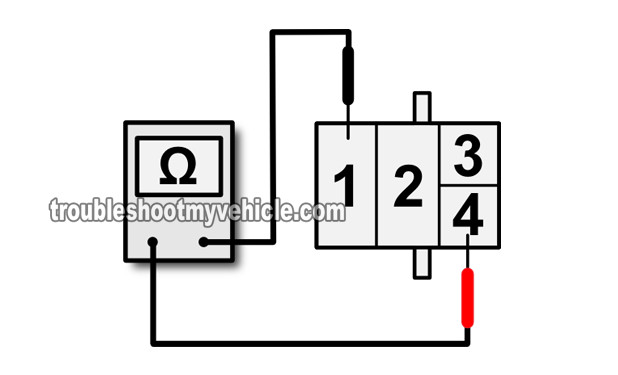
Probe terminals 4 and 1 with your multimeter test leads (see image 2 of 4 in the image viewer).
Your multimeter should register a resistance of about 0.6 to 0.8 Ohms ( Ω). - 5
Probe terminals 4 and 3 with your multimeter test leads (see image 3 of 4 in the image viewer).
Your multimeter should register a resistance of about 0.2 to 0.3 Ohms ( Ω).
This test also test the continuity of the blower resistor thermal fuse.
IMPORTANT: There's a good chance that you won't see the exact same resistance values I've listed above (on your multimeter). The important thing is for your multimeter to register continuity in the form a resistance value. If your multimeter registers OL (Open Loop), then that resistor is bad.
Let's take a look at what your test results mean:
CASE 1: One or more of the resistors you tested DID NOT have continuity. Repeat the tests just to make sure of your test results.
If continuity is not present where indicated in the test steps above then this confirms that the blower motor resistor is bad and needs to be replaced.
CASE 2: All circuits tested had continuity where indicated in the test steps. This is good and is the correct and expected test result that tells you that the blower motor resistor is OK and not the cause of the blower motor speed problem.
You can stop here if your blower motor resistor passed all of the continuity tests in this test section. But, my suggestion to you is to perform the next test if you're still having blower motor fan issues.
The next step indirectly tests the blower switch on the A/C Heater control panel by bypassing the blower resistor with a jumper wire: TEST 2: Using A Jumper Wire To Bypass The Blower Resistor.


