TEST 1: Check The Basics First

To succesfully diagnose a problem in the MAF sensor's wiring, you need to have done a few basic checks.
These are basic pre-checks that check for obvious damage or problems with the MAF sensor and its connector.
Taking the time to check the list below could save you the frustration (and money) of having the replace parts your Ford doesn't need and that won't solve the issue.
Here's the list of the things you should already have checked/confirmed:
- The mass air flow (MAF) sensor itself is not defective. Either because you replaced it with a new one or you have tested it.
- The MAF sensor connector is not broken, or damaged in any way.
- The air duct that connects the air filter canister to the throttle body IS NOT broken or cut. In other words, the duct hose is not damage in any way (which could allow unmetered air into the intake manifold).
- That the round air filter canister, which houses the air filter element and the MAF sensor, IS NOT broken and letting air bypass the MAF sensor.
- The RED has or does not have 12 Volts (VPWR) with the Key On Engine Off (KOEO) and Key On Engine Running (KOER)
- The BLK/WHT wire has or does not have chassis Ground.
Again, making sure that the above are OK or that a problem exists (that needs to be remedied) will help you save a ton of frustration, time and money.
The following tutorial will show you how to check the MAF sensor itself:
- How To Test The Ford MAF (4.2L, 4.6L, 5.4L) (at: easyautodiagnostics.com).
The following simplified wiring-diagrams may also be of help:
- MAF Sensor Circuit Wiring Diagram (1997-1998 4.6L, 5.4L V8 Ford F150, F250 Light Duty) (at: easyautodiagnostics.com).
- MAF Sensor Circuit Wiring Diagram (1999 4.6L, 5.4L V8 Ford F150, F250 Light Duty) (at: easyautodiagnostics.com).
OK, if all of the above check out OK, then your next step is to make check the continuity of the MAF sensor's wires between the PCM connector and the MAF sensor's connector.
TEST 2: Checking Continuity Of The MAF SIG Circuit
As mentioned earlier, of the 4 wires sticking out of the MAF sensor's connector, only 2 wires connect directly to the PCM (Powertrain Control Module = Fuel Injection Computer).
These 2 wires are the TAN/LT BLU (tan w/ light blue stripe) wire and the LT BLU/RED (light blue w/ red stripe) wire.
Of these 2, the LT BLU/RED wire is the one that takes the MAF signal (the MAF sensor creates) back to the PCM.
So, our first test will be to check the LT BLU/RED wire is not open between the MAF connector and the PCM connector.
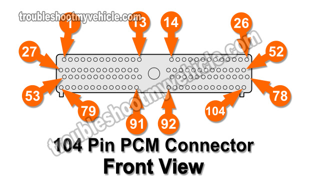
NOTE: The LT BLU/RED wire connects to pin 88 of the PCM 104 pin connector.
IMPORTANT: Do not probe the front of the PCM 104 connector or you'll damage the terminal. This will require that you replace the entire engine wiring harness.
OK, these are the test steps:
- 1
Disconnect the battery negative cable and then unplug the PCM from its connector.
IMPORTANT: The battery negative cable will remain disconnected from the battery negative post for the remainder of the test. - 2
Connect the breakout box to the 104 pin PCM connector only. Do not connect the the Ford 104 pin breakout box to the PCM.
- 3
Place your multimeter in Ohms mode (Ω). We'll be checking the continuity of the circuit by checking its resistance.
- 4
Measure resistance between breakout box pin 88 and the MAF sensor connector terminal that connects to the LT BLU/RED wire.
The LT BLU/RED wire is the wire that connects to terminal 88 of the PCM 104 pin connector. - 5
Your multimeter should register 5 Ohms or less if the circuit is OK and has continuity.
Let's take a look at what your test results mean:
CASE 1: Your multimeter registered 5 Ohms or less. This test result tells you that the LT BLU/RED wire is not ‘open’ between the MAF sensor connector and the PCM 104 pin connector.
Your next step is to check the power circuit of the MAF sensor. For this test go to: TEST 3: Checking Continuity Of The 5 V Reference Circuit.
CASE 2: Your multimeter DID NOT register 5 Ohms or less. If the resistance value is in the thousands of Ohms or your multimeter registered OL (over limit), then the wire is ‘open’.
This also means that the signal the MAF sensor is creating IS NOT reaching the PCM.
Your next step is to repair the wire since, somewhere between the PCM connector and the MAF senosr connector, this wire is broken. Repairng this ‘open’ in the LT BLU/RED wire will get the MAF signal to reach the PCM and solve the MAF issue your Ford is currently experiencing.


