")
The blower motor switch is a pretty easy component to test with a multimeter in Ohms mode (Ω).
I'll show you how in a step-by-step way so that you can find out if it's bad and needs to be replaced or not.
This tutorial only applies to the vehicles listed in the ‘Applies To:’ box on the right column. To aid you in further knowing if this tutorial applies to your Ford car, mini-van, pickup or SUV, if your vehicle uses one of the following blower motor switch numbers, this tutorial applies to your vehicle:
- Airtex/Wells 1S3046.
- Duralast SW3316.
- Four Seasons 20046.
- Motorcraft YH1670.
- Standard Motor Products: HS333.
Contents of this tutorial:
The following tutorials compliment the blower motor switch tests in this tutorial and may be of help:
- How To Test The Blower Motor Resistor (Ford 4.6L, 5.4L).
- How To Test The Blower Motor (Ford 4.6L, 5.4L).
Basics Of Troubleshooting The Blower Control Switch
")
The blower motor switch works by rerouting the current that passes through it from one internal contact to another.
To be more specific, as you turn the blower speed knob, the blower switch ‘opens’ and ’closes’ two contacts. The opening and closing of these contacts is what diverts the incoming blower motor current to different resistors within the blower motor resistor assembly.
I'll explain this a bit further with an example of what happens when you turn the blower fan speed knob from OFF to LO:
- When the blower fan is in the LO position:
- Battery power is available on terminal 2 of the blower switch connector. The BLK/ORG wire is the one that connects to terminal 2 of the blower motor switch.
- Inside the blower motor switch this battery power goes nowhere.
- When you turn the blower fan switch to the M1 position:
- Battery power is available on terminal 2 of the blower switch connector (BLK/ORG wire).
- This battery power is now diverted to terminal 3 of the blower switch harness connector (LT GRN/WHT wire).
- In tech speak: circuit 2 and 3 is now considered ‘closed’.
- The end result is that your Ford's blower motor now runs in M1 speed.
- When you turn the blower fan switch to the M2 position:
- Battery power is available on terminal 2 of the blower switch connector (YEL/RED wire).
- This battery power is now diverted to terminal 4 of the blower switch harness connector.
- In tech speak: circuit 2 and 4 is now considered ‘closed’.
- In tech speak: circuit 2 and 3 is now considered ‘open’.
- The end result is that your Ford's blower motor now runs in M2 speed.
- This interruption and diverting of battery power goes on for all of the other blower fan speeds.
Since these are mechanical connections the blower switch is making to open and close these circuits, over time and use these contacts become pitted and covered in carbon (from the electrical arching that occurs when the contacts close). When this happens, one or several of the blower fan speeds stop working.
The cool thing is that diagnosing/troubleshooting the blower switch isn't hard. The following circuit descriptions will help:
| Blower Switch Circuit Descriptions | ||
|---|---|---|
| Pin | Wire Color | Description |
| 1 | BLK | Chassis Ground. |
| 2 | ORG/BLK | Input From Blower Motor. |
| 3 | YEL | M2 Speed Output. |
| 4 | DK GRN | M1 Speed Output. |
NOTE: There's a good chance that the color of the wires described above DOES NOT match what's on your particular vehicle. This is no cause for concern since the circuit descriptions are the same for all of the Ford vehicles covered by this repair tutorial.
Where To Buy The Blower Switch And Save
You don't have to buy the whole A/C-Heater Control Panel to replace the blower control switch since the switch is removable. If you're interested in the original Ford Motorcraft blower switch or on an after-market part (and save), the following links will help you comparison shop.
The following links will help you comparison shop for the blower motor control switch and the connector:
 29%
29%


Wondering if the above switches fit your particular Ford? Don't worry, once you get to the site, they'll make sure it fits by asking you the specifics of your vehicle. If they don't fit, they'll find you the right one.
TEST 1: Checking Continuity Of The Blower Switch Fan Speeds
")
")
")
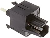
The continuity tests I'm describing below depend on identifying the correct blower switch male spade terminals.
I've created the illustrations in the image viewer to aid you in identifying them and I'll point out which one applies in each specific test below.
As you test for continuity, your multimeter should register about 1 Ohm or less. If your multimeter registers OL (Open Loop), then that circuit (within the blower switch) is bad and the blower switch needs to be replaced.
IMPORTANT: All multimeter continuity tests described in this test section are done on the blower switch's male spade metal terminals and not on the switch's connector. All the illustrations (in the image viewer) are of the blower switch itself and NOT of the connector (see image 4 of 4).
OK, let's get started:
- 1
Remove the A/C-Heater control panel from the dash and unplug the blower motor switch from its harness connector. Set your multimeter to Ohms mode (Ω).
Don't have a multimeter or need to upgrade yours? Check out my recommendation: Buying A Digital Multimeter For Automotive Diagnostic Testing (found at: easyautodiagnostics.com). - 2
With the blower switch knob set to the M1 position.
You should have continuity between 2 and 3 (see image 1 of 4 to identify the proper male spade terminals to probe).
NOTE: See image 4 of 4 to further identify the blower switch terminals. - 3
With the blower switch knob set to the M2 position.
You should have continuity between 2 and 4 (see image 2 of 4 to identify the proper male spade terminals to probe). - 4
With the blower switch knob set to the HI position.
You should have continuity between 2 and 1 (see image 3 of 4 to identify the proper male spade terminals to probe).
Let's take a look at what your test results mean:
CASE 1: One or more of the circuits tested DID NOT have continuity as you turn the blower switch to the indicated blower speeds. Double check your multimeter connections and repeat the tests.
If continuity is not present where indicated in the test steps above and this lack of continuity coincides with the blower fan speed that's not working on your Ford pickup or SUV, then you've found the cause of the problem.
Replace the blower switch in the A/C-Heater control panel with a new one to solve the problem. To comparison shop for the blower control switch, take a look at this section here: Where To Buy The Blower Switch And Save.
CASE 2: All circuits tested had continuity where indicated in the test steps. This is good and is the correct and expected test result that tells you that the blower fan switch (in the A/C-Heater control panel) is NOT defective.
Your next step is to bypass the blower resistor using a simple jumper wire. For this test go to: TEST 2: Using A Jumper Wire To Bypass The Blower Switch.