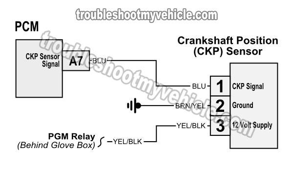
Crankshaft Position (CKP) Sensor Wiring Diagram

NOTE: The above crankshaft position sensor wiring diagram applies only to 2001, 2002, 2003, 2004, 2005 1.7L Honda Civic.
Here's a brief description of the crank sensor's 3 circuits (wires):
- BLU wire:
- Outputs the crankshaft position (CKP) signal.
- The crankshaft position (CKP) signal is an analog voltage signal that can be measured with a multimeter (or an oscilloscope).
- BRN/YEL wire:
- Cranks sensor's Ground.
- YEL/BLK wire:
- Supplies 12 Volts DC.
- These 12 Volts come from the PGM relay.
The crankshaft position (CKP) sensor can be very accurately tested with a multimeter. You can find the step-by-step testing instructions here: How To Test The Crank Sensor (2001-2005 1.7L Honda Civic).

Where To Buy The Crank Sensor And Save
The best place to comparison shop and get an idea of how much your 1.7L Honda Civic's crankshaft position sensors costs (and how much you can save) is here:
Not sure if the above crankshaft position sensor fits your particular 1.7L Honda Civic? Don't worry, once you get to the site, they'll make sure it fits by asking you the particulars of your vehicle. If it doesn't fit, they'll find you the right one.
More 1.7L Honda Civic Tutorials
You can find a complete list of tutorials for you Honda 1.7L equipped car here: 1.7L Honda Civic Index Of Articles.
Here's a small sample of the tutorials you'll find in the index:
- Maintenance Required Light Reset (2001-05 1.7L Honda Civic).
- How To Do A Cylinder Balance Test (2001-2005 1.7L Honda).
- How To Test Trouble Code P0141 (2001-2005 Honda 1.7L).
- How To Test The TP Sensor (2001-2005 1.7L Honda Civic).
- How To Test Trouble Code P0135 (2001-2003 Honda 1.7L).

If this info saved the day, buy me a beer!


