TEST 1: Checking The MAP Sensor Signal
The very first thing that you and I need to do, to see if the manifold absolute pressure (MAP) sensor is bad, is to check that it's producing a MAP signal that the PCM can use.
As mentioned in the previous page, the only way to be absolutely sure that the MAP sensor is bad or not, is to test it independent of engine vacuum.
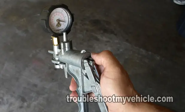
So, you'll need a vacuum pump to do it. Now, if you don't have a vacuum pump, you can run down to your local auto parts store and rent one (that is if you live nearby an Auto Zone or O'Reilly Auto Parts Store).
NOTE: The MAP sensor must remian connected to its electrical connector. You'll need to either back-probe the connector or use a wire piercing probe to get to the MAP signal voltage inside the wire. You can see an example of this tool here: Wire Piercing Probe Tool
OK, this is what we'll do:
- 1
Remove the MAP sensor from its place. Reconnect the MAP sensor to its electrical connector.
- 2
Place your multimeter in Volts DC mode.
- 3
Connect the red multimeter test lead to the wire labeled with the letter B (see photo above).
- 4
Connect the black multimeter test lead directly on the battery negative (-) post.
- 5
Turn the key to the On position but don't start the engine.
At this point your multimeter should read a voltage between 4.5 to 5 Volts DC. - 6
Manually apply vacuum with a vacuum pump to the MAP sensor's vacuum inlet port using a suitable vacuum hose.
NOTE: If you don't have a vacuum pump, no problem. You can use your mouth to apply vacuum to the vacuum inlet port. - 7
The multimeter should show an decreasing voltage as you apply vacuum with the vacuum pump.
If you're using your mouth to apply vacuum, you should see the voltage decrease when applying vacuum and seeing the voltage return to its original voltage when you release said vacuum.
If you're using a vacuum pump, you should see the following values:
At 0 in Hg - 4.8V (this is no vacuum applied to the MAP sensor).
At 5 in Hg - 3.9V.
At 10 in Hg - 3.1V.
At 15 in Hg - 2.1V.
Let's interpret your test results:
CASE 1: The voltage decreased as you applied vacuum. This is the correct test result and it tells you that the MAP sensor is OK and not the true cause of the MAP sensor codes.
This also confirms that the MAP sensor is getting power (5 Volts) on wire C and Ground on wire A.
CASE 2: The voltage DID NOT decrease as you applied vacuum. This usually means that the MAP sensor is bad but we'll need to make sure that the MAP sensor is getting both power and Ground.
For this test, go to: TEST 2: Making Sure The MAP Sensor Is Getting 5 Volts.
TEST 2: Making Sure The MAP Sensor Is Getting 5 Volts

So far, you've confirmed (in TEST 1), that the manifold absolute pressure (MAP) sensor is NOT producing a signal.
The next step, before condemning the MAP sensor as bad, is to make sure that it's getting both power and Ground.
In this test step, we'll check that it's getting power (which comes in the form of 5 Volts) on circuit (wire) C.
One last thing, this voltage comes directly from the PCM, so be careful and don't intentionally or accidentally short this wire to battery voltage.
This is what you'll need to do:
- 1
Place your multimeter in Volts DC mode.
- 2
Disconnect the MAP sensor from its electrical connector.
- 3
Connect the red multimeter test lead to the wire labeled with the letter C.
- 4
Connect the black multimeter test lead directly on the battery's negative (-) terminal.
- 5
Have a helper turn the key to the On position, but don't crank or start the engine after the multimeter test leads have been set up.
- 6
Your multimeter should register 4.5 to 5 Volts DC if the VIO/WHT wire is feeding the manifold absolute pressure (MAP) sensor with power.
Let's take a look at your test results:
CASE 1: 4.5 to 5 Volts are present in the C circuit wire. This is the correct test result and it confirms that the PCM is supplying power to the manifold absolute pressure (MAP) sensor.
The next step is to make sure that the PCM is providing Ground to the MAP sensor. For this test, go to: TEST 3: Making Sure The MAP Sensor Is Getting Ground.
CASE 2: 4.5 to 5 Volts ARE NOT present. Without these 5 Volts the MAP sensor will not function. Recheck your multimeter connections and retest.
If the multimeter still does not register 4.5 to 5 Volts, then you've found the reason for the MAP sensor code/failure.
Although, it's beyond the scope of this tutorial to test for this missing voltage, the most likely cause will be an ‘open-circuit’ problem between the PCM connector and the MAP sensor connector.

