Page 1 of 2
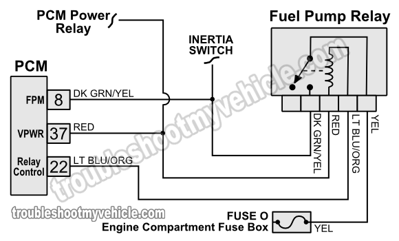
Fuel Pump Relay Wiring Diagram

NOTE: The wiring diagram illustrations in this article cover only: 1992-1993 Gasoline 4.9L, 5.0L, and 5.8L F150, F250, and F350 with dual/single gasoline tank.
Fuel Pump Relay Diagnostic/Troubleshooting Notes:
- The YEL wire:
- Should have 10 to 12 Volts DC with Key On Engine Off (KOEO) or Key On Engine Running (KOER).
- The RED wire:
- Should have 10 to 12 Volts DC while KOEO or KOER.
- This voltage comes from the PCM power relay.
- The DK GRN/YEL wire:
- Should have 10 to 12 Volts DC for a few seconds when turning the key to the On position.
- Should have 10 to 12 Volts when cranking the engine.
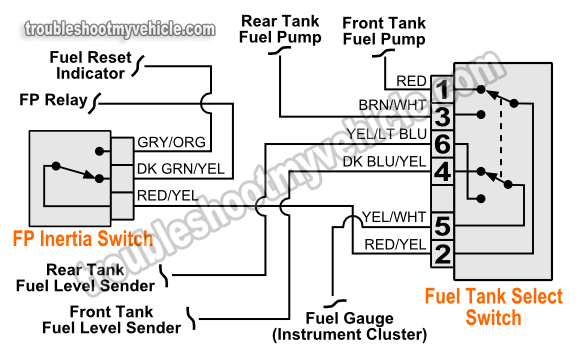
Fuel Tank Select Switch Wiring Diagram

Fuel Pump Inertia Switch Diagnostic/Troubleshooting Notes:
- The DK GRN/YEL wire:
- Should have 10 to 12 Volts DC while cranking the engine.
- This power comes from the fuel pump relay.
- The RED/YEL wire:
- Should have 10 to 12 Volts DC while cranking the engine (if the inertia switch IS NOT tripped).
- Inertia Switch (unplugged from its connector):
- Continuity should exist between pin that connects to DK GRN/YEL wire and pin that connects to RED/YEL wire (if switch IS NOT tripped).
Fuel Tank Select Switch Diagnostic/Troubleshooting Notes:
- The RED/YEL wire should have 10 to 12 Volts DC while cranking the engine.
- Front tank selected (switch unplugged from its connector):
- Continuity should exist between pin 1 and pin 2.
- Continuity should exist between pin 4 and pin 5.
- Pin 3 and pin 2 should be ‘open’.
- Pin 6 and pin 5 should be ‘open’.
- Rear tank selected (switch unplugged from its connector):
- Continuity should exist between pin 3 and pin 2.
- Continuity should exist between pin 6 and pin 5.
- Pin 1 and pin 2 should be ‘open’.
- Pin 4 and pin 5 should be ‘open’.
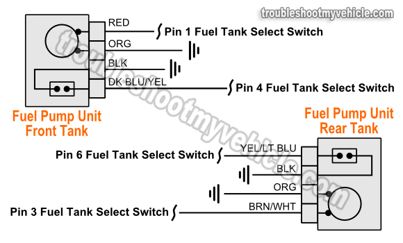
Fuel Pump Unit Wiring Diagram (Dual Tanks)

NOTE: The above illustration only applies to dual tank equipped Ford pickups. The single tank equipped fuel pump wiring diagram is found in the next page.
